Robosub Autonomous Underwater Vehicle (AUV)
Designed and manufactured critical mechanical subsystems for a competition AUV, including a fully sealed front camera enclosure.
01
Ground up redesign
Background
Nemo is a fully autonomous underwater vehicle (AUV) developed for the RoboSub competition, designed to complete tasks such as object detection, navigation, and acoustic localization. The project aimed to improve upon our previous vehicle (Marlin) that suffered from instability, difficult maintenance, and limited modularity. As a member of the mechanical team, I contributed to the design and manufacturing of the vehicle, with a primary focus on developing a new ground up front camera enclosure and supporting the broader structural system development.
Visualization of Nemo subassemblies
New Vs Old
Comparison between our old sub Marlin (left) and our new design (Nemo) on the right
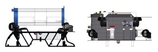
sub comparison
02
Front Camera Enclosure
Designing the Enclosure
I joined the mechanical team at a time when we had a massive project at early design stages. I took on the most complex sub assembly of our entire submarine. At the time, I had never used any CAD software before and had to learn and fail quickly. I initally sketched my ideas for our redesigned modularly camera enclosure. I checked my sealing surfaces for my theoretical design to ensure it could all properly seal and prevent water ingress. After, I jumped into learning CAD and designing all at once. I created 3 different back and front plate designs based on my initial sketch plans. This included different ways to incorporate the 'ears' onto our design. The 'ears' held together our entire camera enclosure under pressure, so I had to be sure it would withstand the relevant pressures and dynamics. Therefore, I did some basic hand calculations and checked those calculations via fea to ensure our maximum stress did not exceed yeild of our aluminum plates and that our deflection was acceptable to properly apply preload to the threaded rods. After designing, we created drawings and chose Type 3 anodization to prevent galvanic corrosion when our aluminum backplate interfacing with our carbon fiber meb was immersed in ocean salt water. In the next section is a view of one drawing sent for manufacturing.
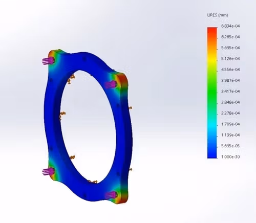
back plate fea
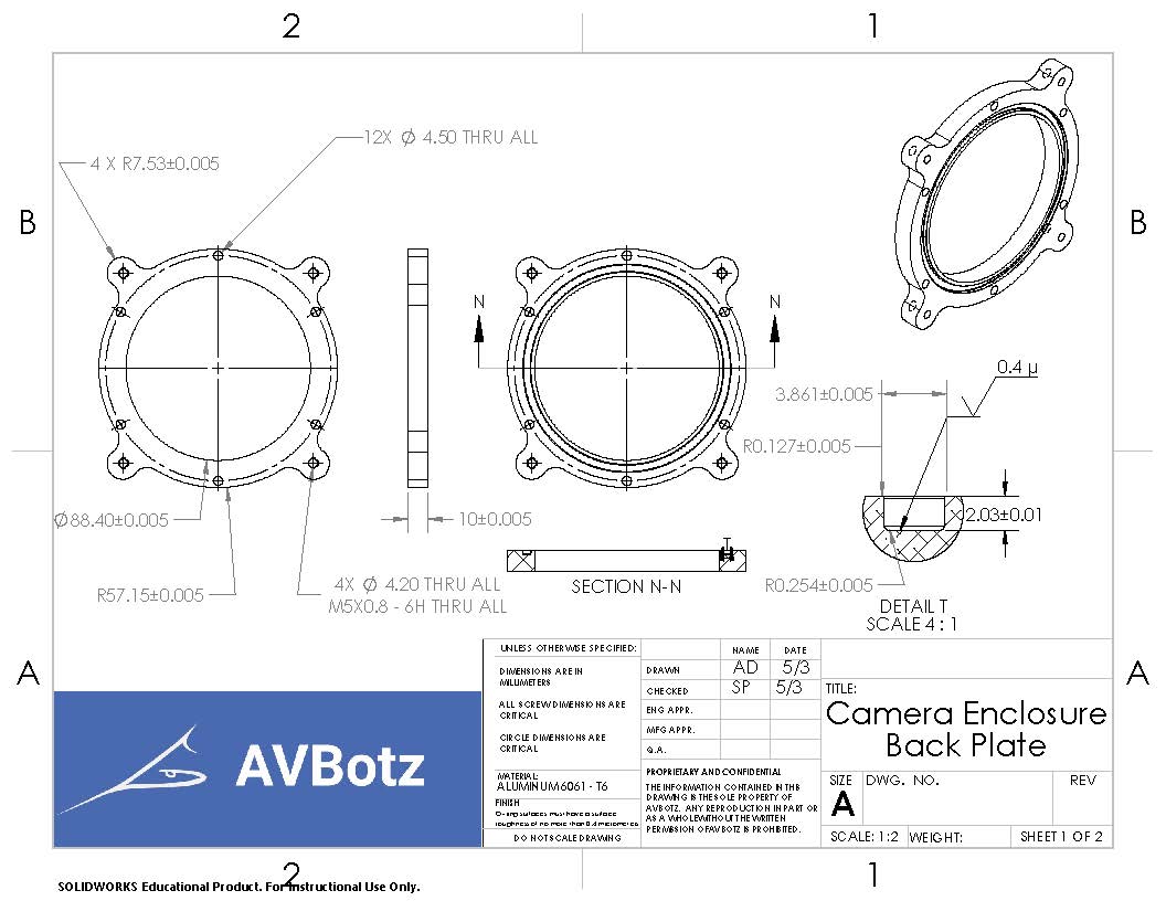
Camera Enclosure drawing for Datron to manufacture
The final back plate design sent for manufacturing ->. After modeling the parts and creating an assembly, I created a bill of materials to understand total assembly cost. After approval and go ahead from our business team, I created the drawings and go them checked by other members of the mechanical team. We then sent them to our sponsor for manufacturing.
back plate
Layup timelapse
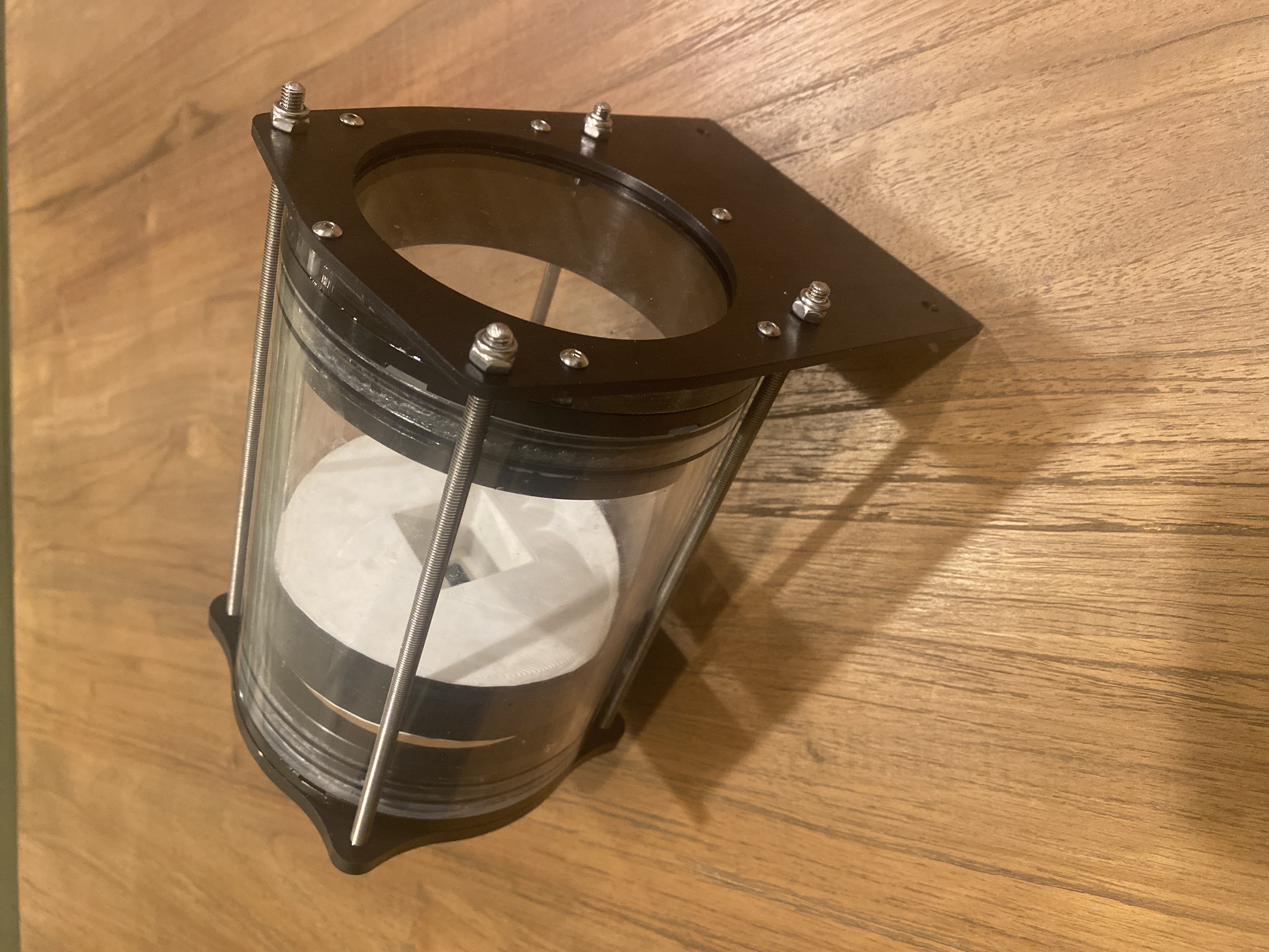
Completed Assembled Camera Enclosure
Camera Enclosure integration initial MEB seal test
03
Takeaway
Key Results
In 4 months, I went from never opening a CAD software to having parts in hand, machined, and anodized ready for assembly. It was a challenge and priviledge to watch a new submarine come together. I also worked on foam tooling (via hot wire foam cutting and laser cut plywood guides), carbon fiber composite layups, metallics bonding, and so much more. Most of all, I greatly appreciate the wonderful people in AVBotz that were smart, capable, and a joy to learn with. There is more information on the entire submarine and more in dpeth explanations in the journal papers below and on the AVBotz website. Take a look!