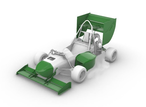
Cal Poly Racing FSAE Nose Cone
Designed and manufactured critical mechanical subsystems for a competition AUV, including a fully sealed front camera enclosure.
01
Formula Overview
Background
Cal Poly Racing is a competitive SAE Collegiate Design Series (CDS) team where over 100 engineers design, manufacture, and test two race vehicles for international Formula SAE and Baja SAE competitions across the United States. The program emphasizes hands-on engineering, rapid iteration, and real-world problem solving beyond the classroom, requiring members to take full ownership of design, manufacturing, and performance. The Formula SAE vehicle is built around a lightweight and highly optimized carbon fiber monocoque, integrating advanced composites, structural analysis, and vehicle dynamics into a single cohesive system. Development is divided into specialized subsystems including Aero, Battery Systems, Brakes, Chassis, Circuit Boards, Driver Controls, Drivetrain, Electronics Packaging, Firmware, High Voltage Electronics, Manufacturing, Materials, Sensor Integration, Suspension, Testing, and Wire Harnessing. Each subsystem operates with a high degree of technical depth while remaining tightly integrated with the overall vehicle architecture.
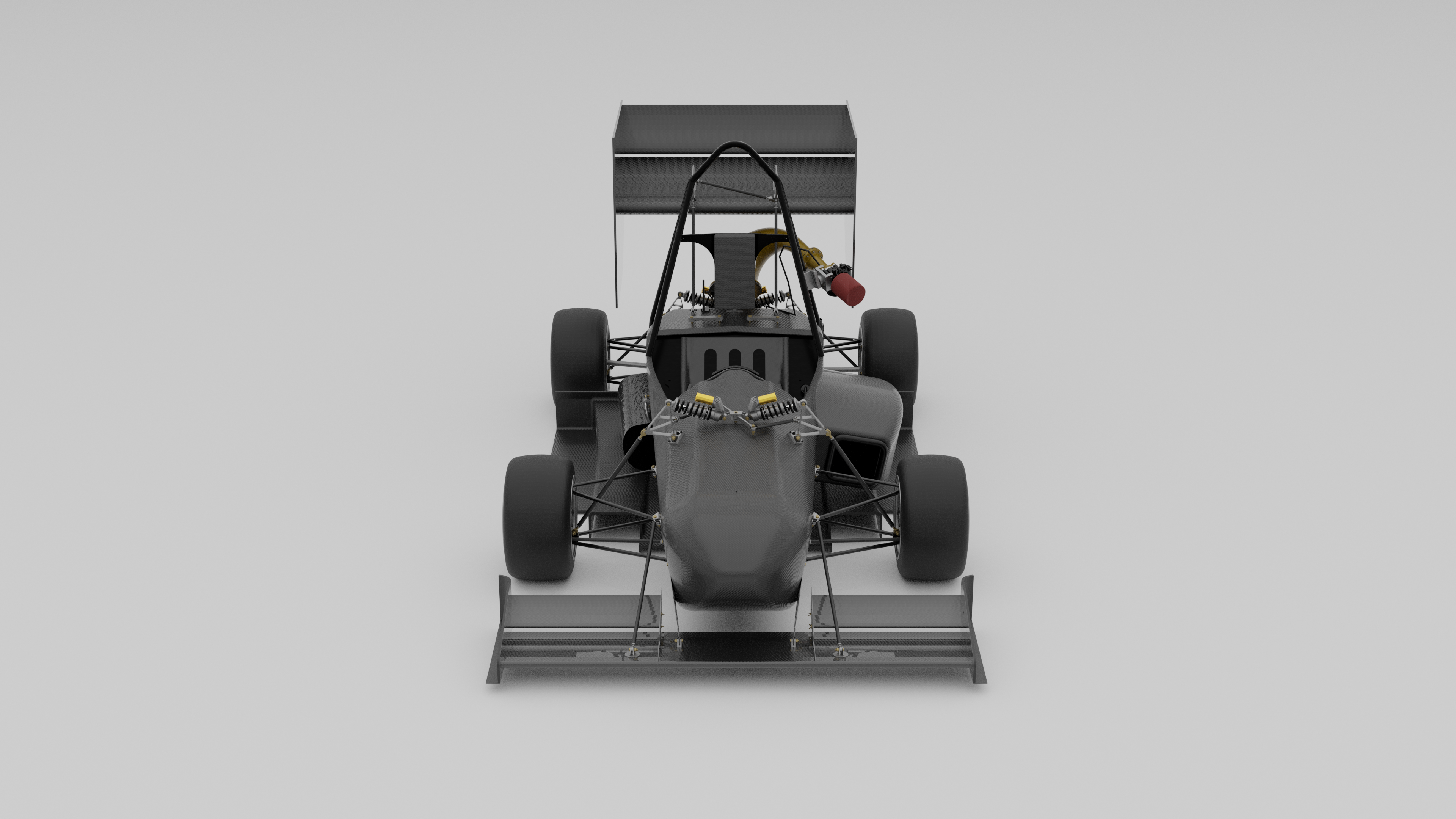
Full Car Render
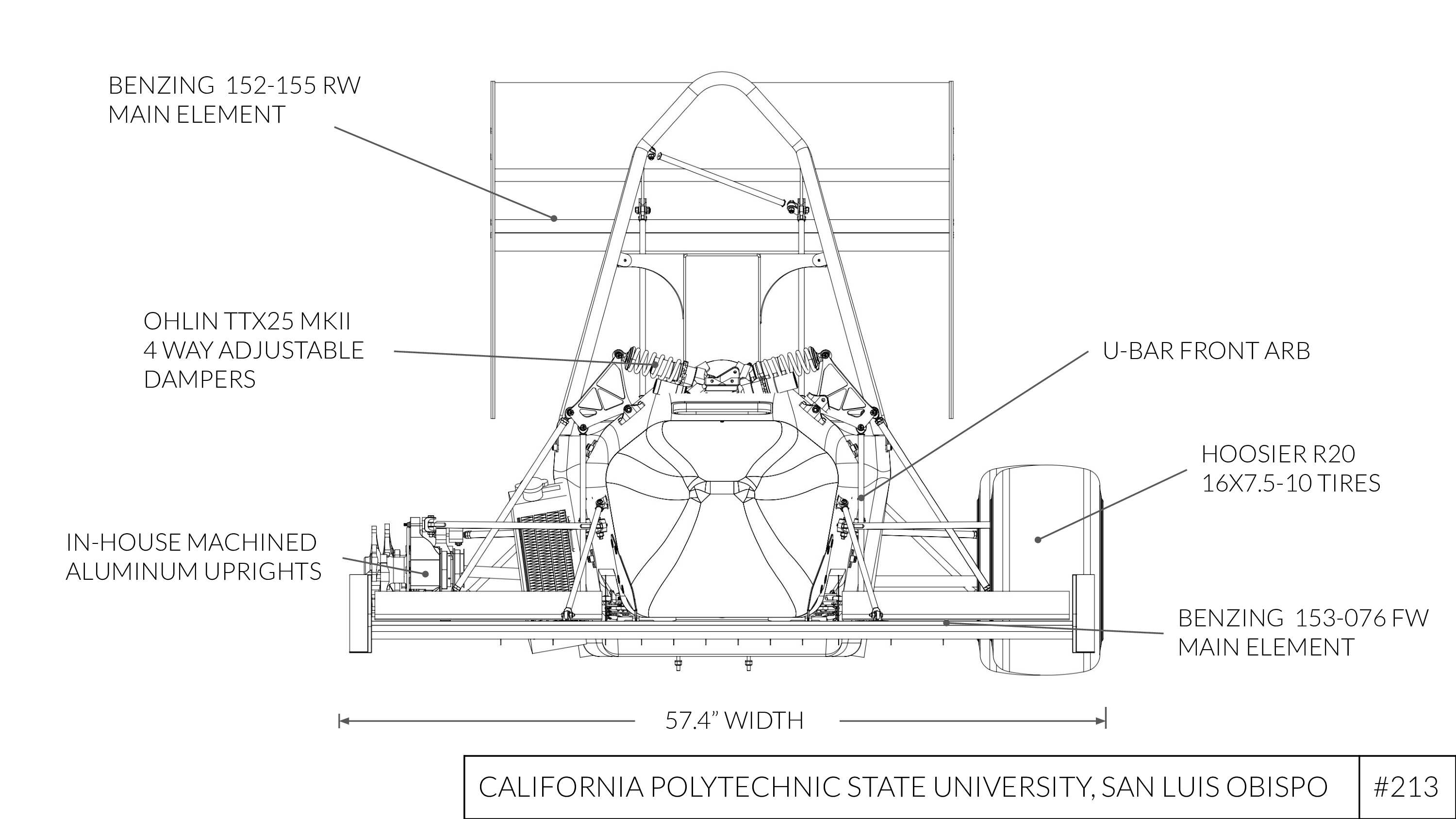
FV
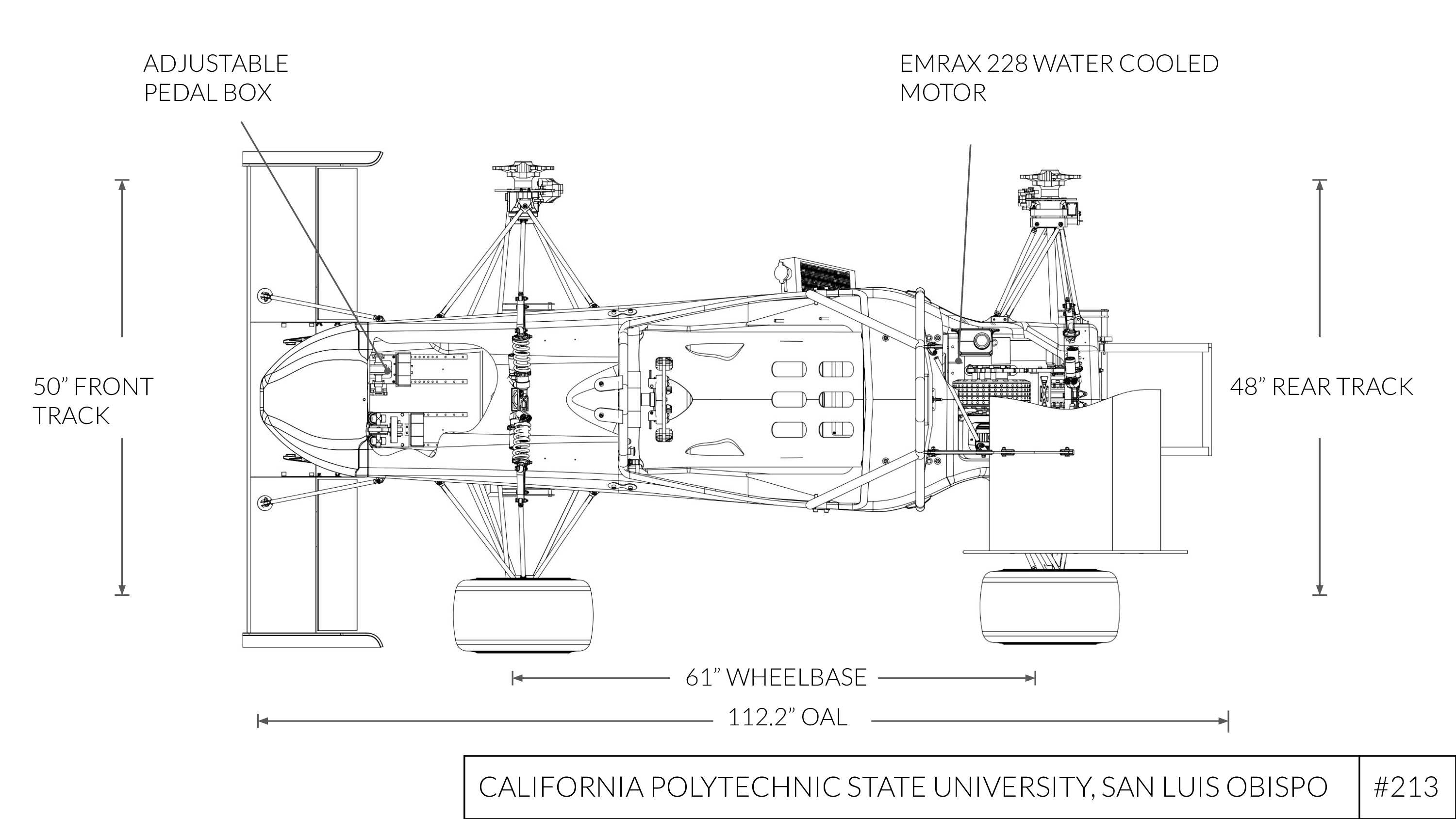
TV
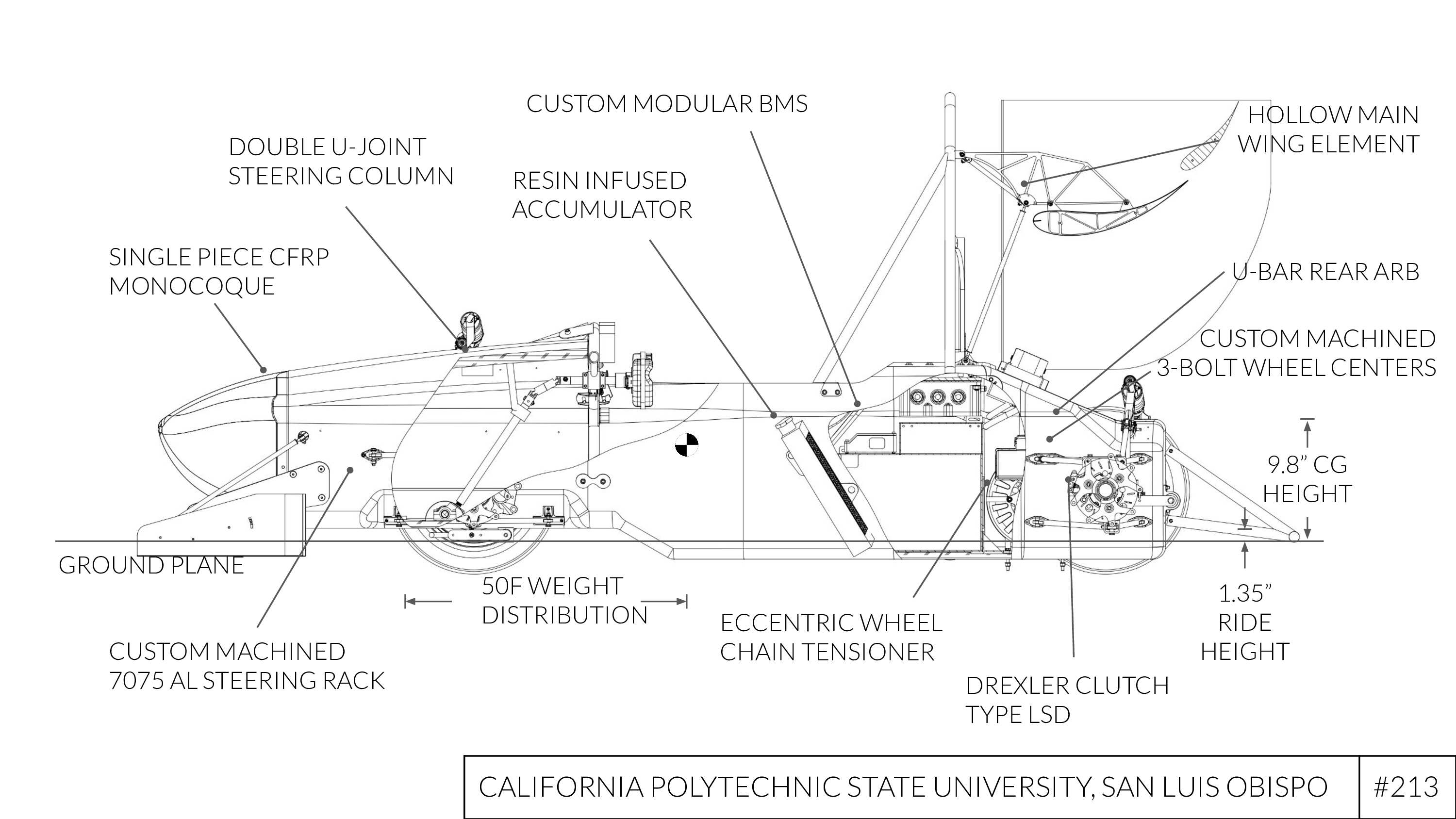
SV
Joining the Aerodynamics Team
My previous carbon fiber composite experience and experience with complex subsystems drew me to the aerodynamics subsystem. Furthermore, there was a lot of opportunity for a large amount of ownership for new engineers. One of my largest projects for the team, was developing a new tooling method for our team that could be done faster. I took this project on under tight competition deadlines which required new processes.
sub comparison
02
Traditional Team Tooling vs. Accelerated Tooling
New Method of Tooling
Traditionally, the aerodynamics team used cnc foam cut tooling. This method allowed for the carbon fiber tool to be layed up on the foams surface and then part layups on the created tool. However, I took on this project with tight competition deadlines. The current process required a shopbot (foam cutter) certificaiton tag along with a large enough block of foam to create a tool. This option was not feasible for our team given the time constraints and shop resources. I developed a method of tooling that used spliced sections of the nosecone that fit within the shops available printers. We then aligned these sections wwith metal pins creating the buck for our tooling layup.
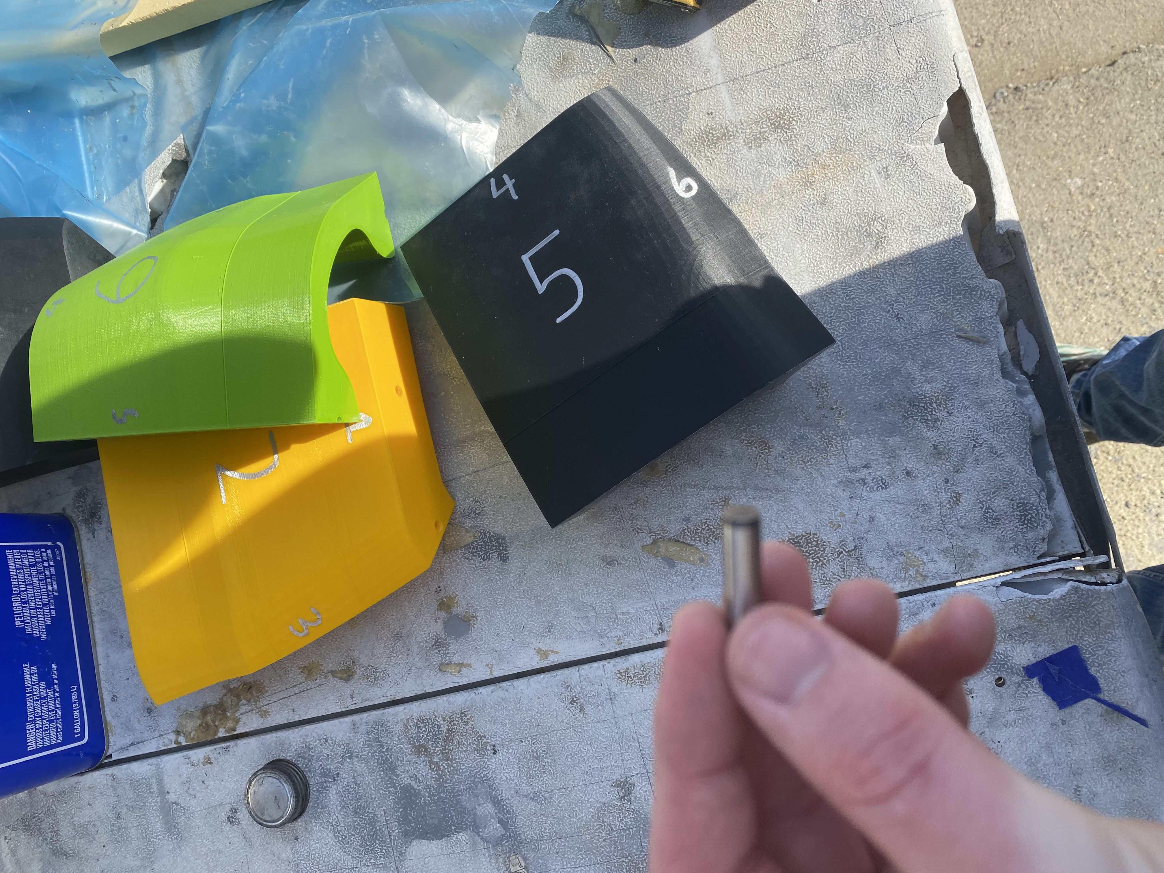
3D printed nose cone sections for tooling
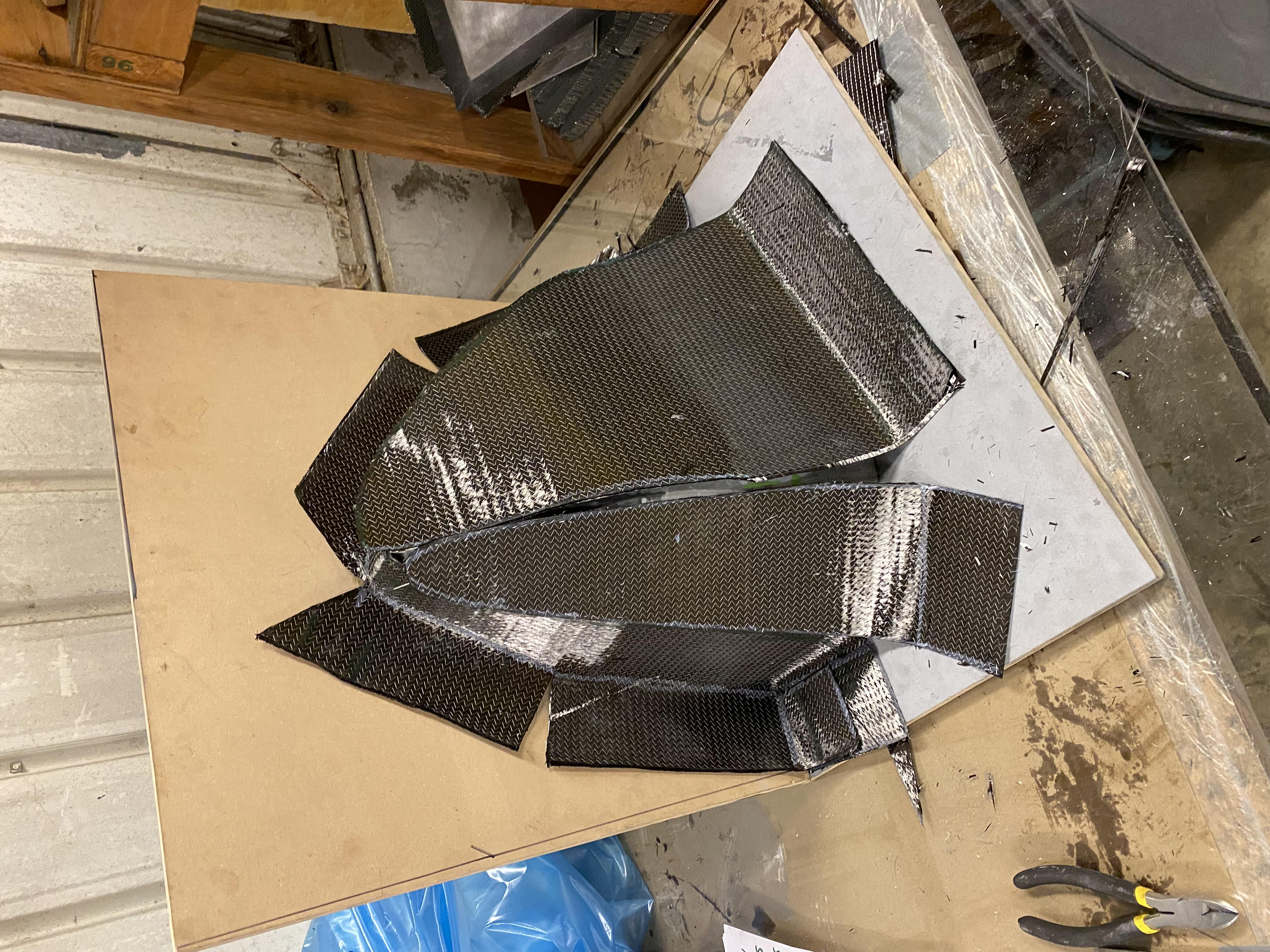
Nose Cone Tooling Prep and Nose Cone Layup
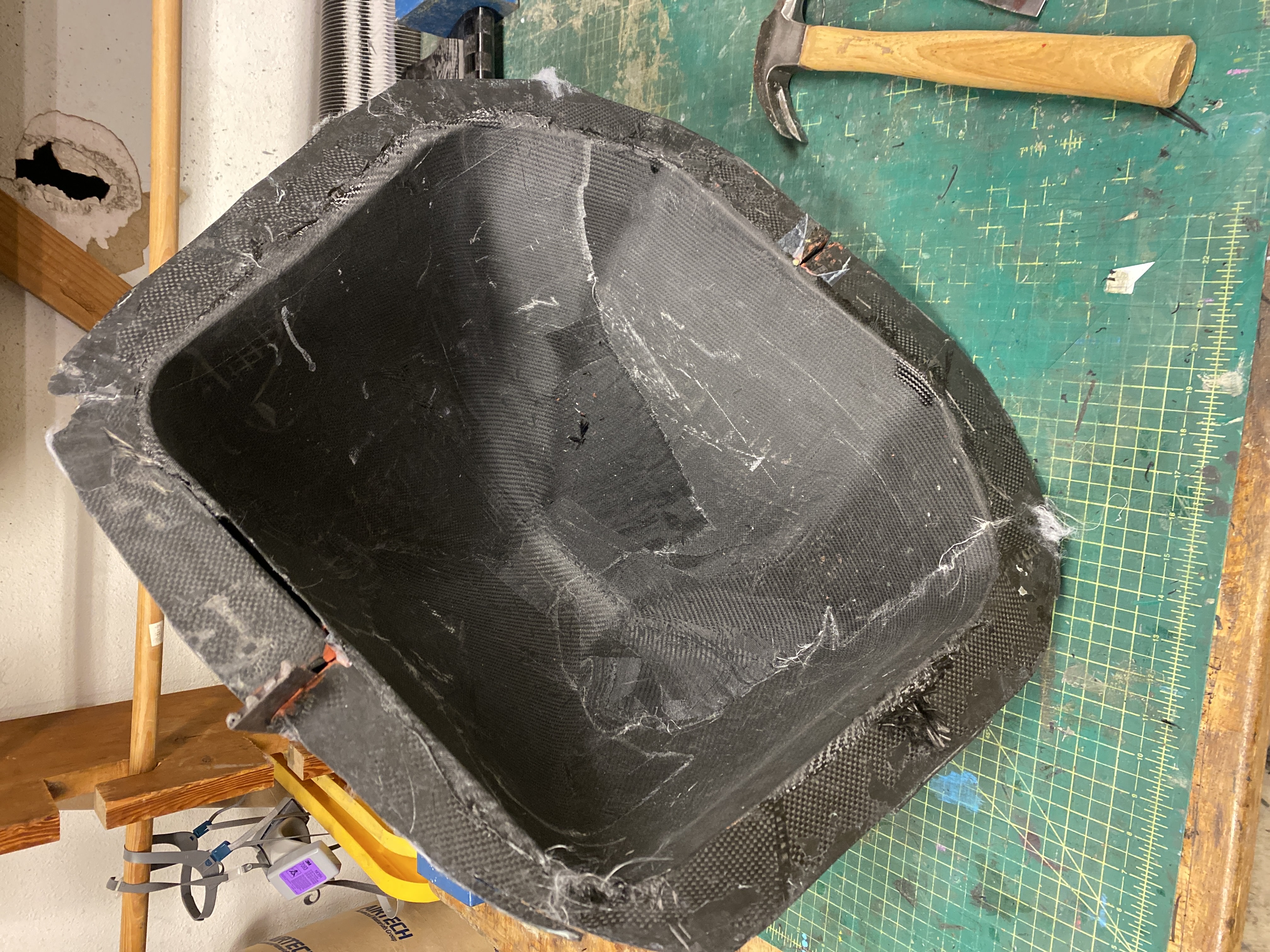
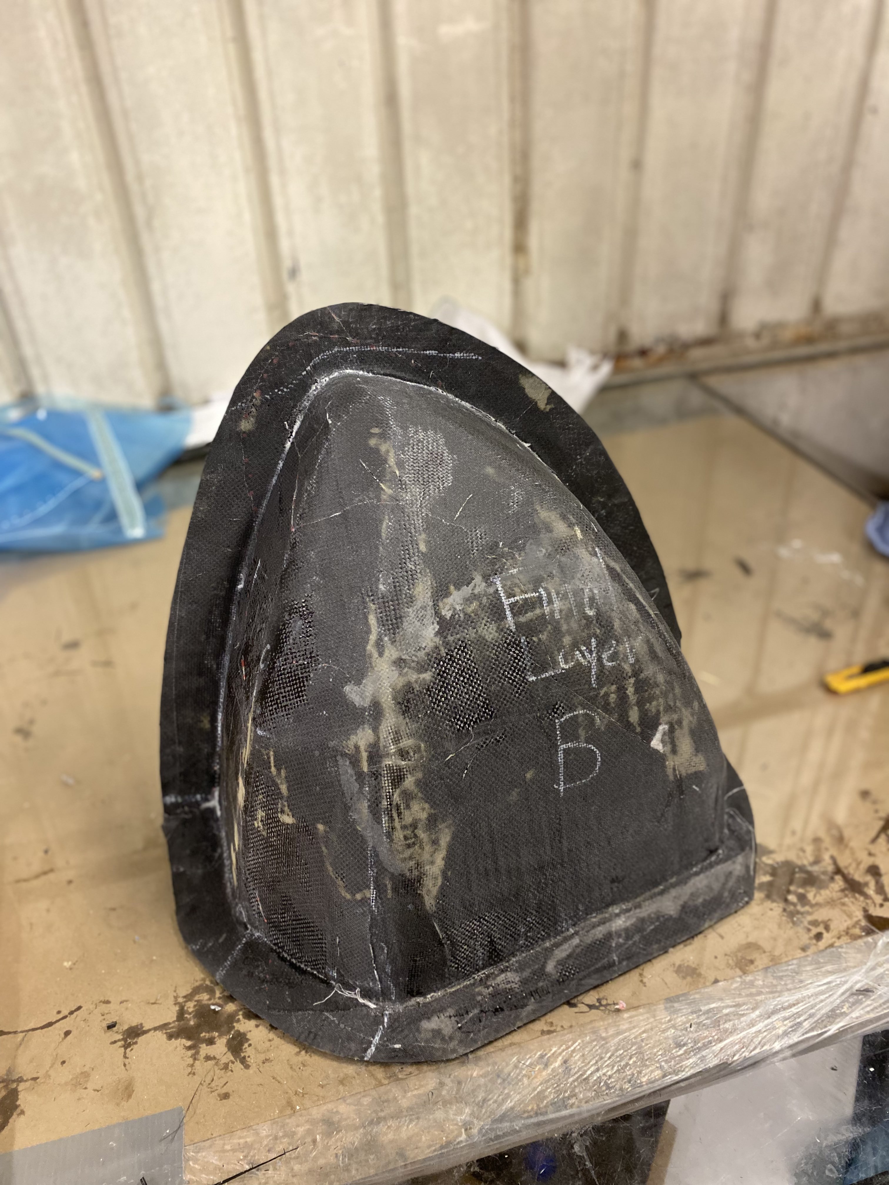
The nose cone sections were sanded, aligned, and bonded. I then cut and nailed 2 pieces of mdf together at a 90 degree angle with the angle of the nosecone surfaces ensuring alignment. Each half of the nose cone buck was epoxied onto the mdf boards. After, thin layers of bondo were applied and sanded to minimize the presence of 3D printed layer lines. After bondo, a think layer of epoxy was applied as a last coat over the bondo to provide a uniform bonding and layup surface. The nose cone layup consisted of previously determined and tested layup schedules. These were quite thin layup schedules consisting of only 2-3 plys of 0 45 and 90 carbon. The nose cones requirments only consisted of covering our impact attenuator, introducing clean air flow over our chassis, and meeting our leading edge radius requiremnt. Therefore as a non structural part it did not need to support structural loads. After 2 nose cones were produced, a nose cone with core in long lofted sections was done to make a more rigid nose cone. A picture of the cored nose cone is below.

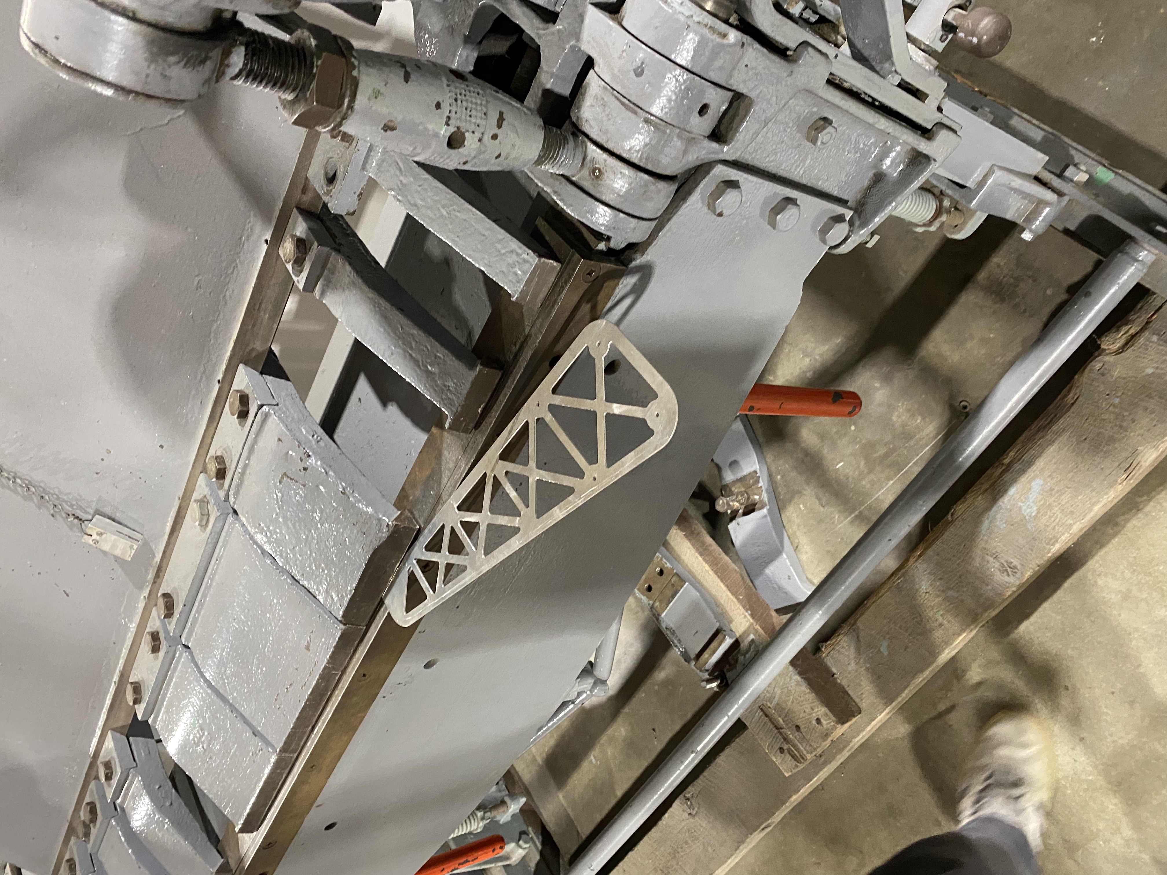
back plate
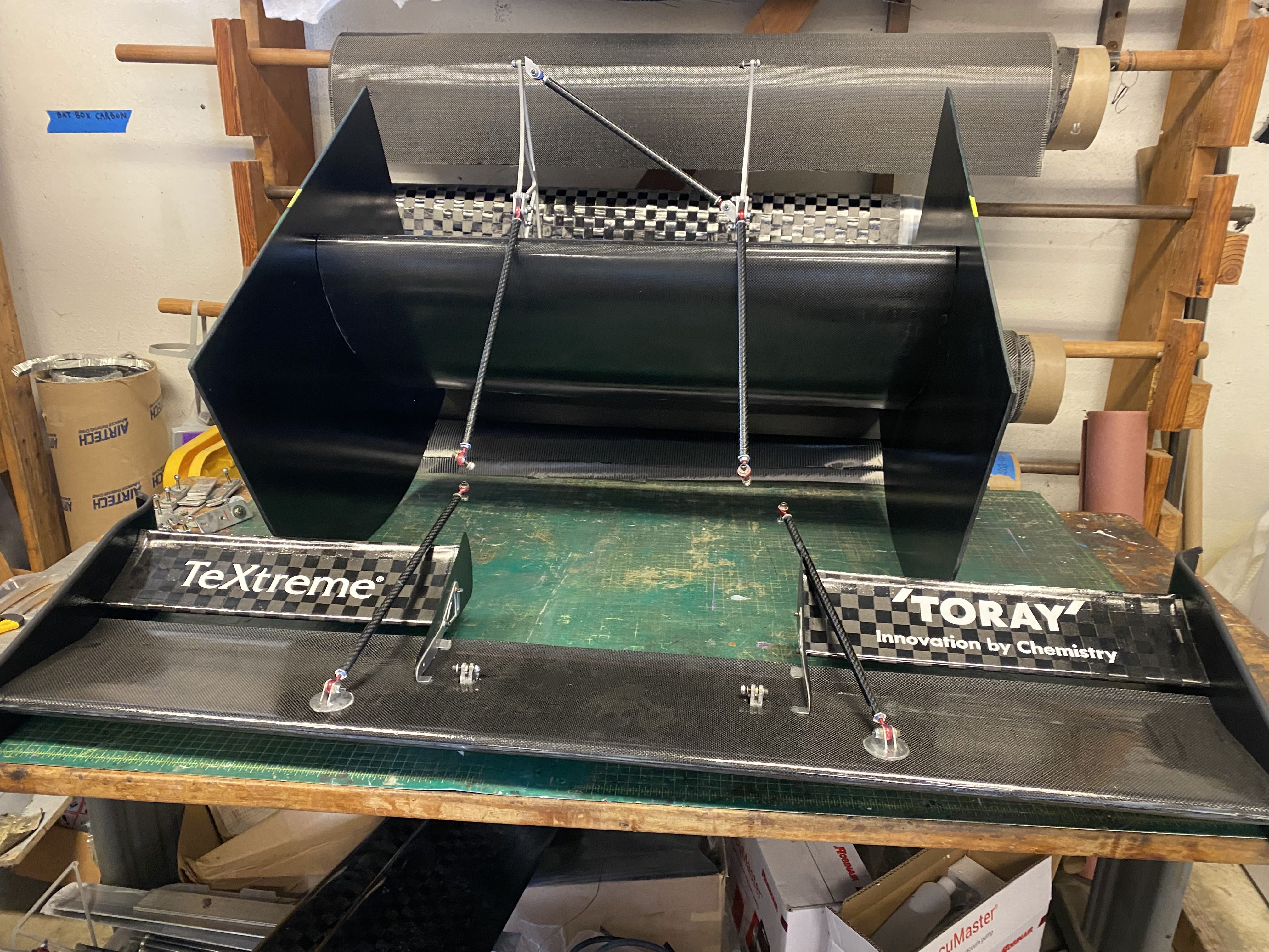
Nose Cone Tooling Layup
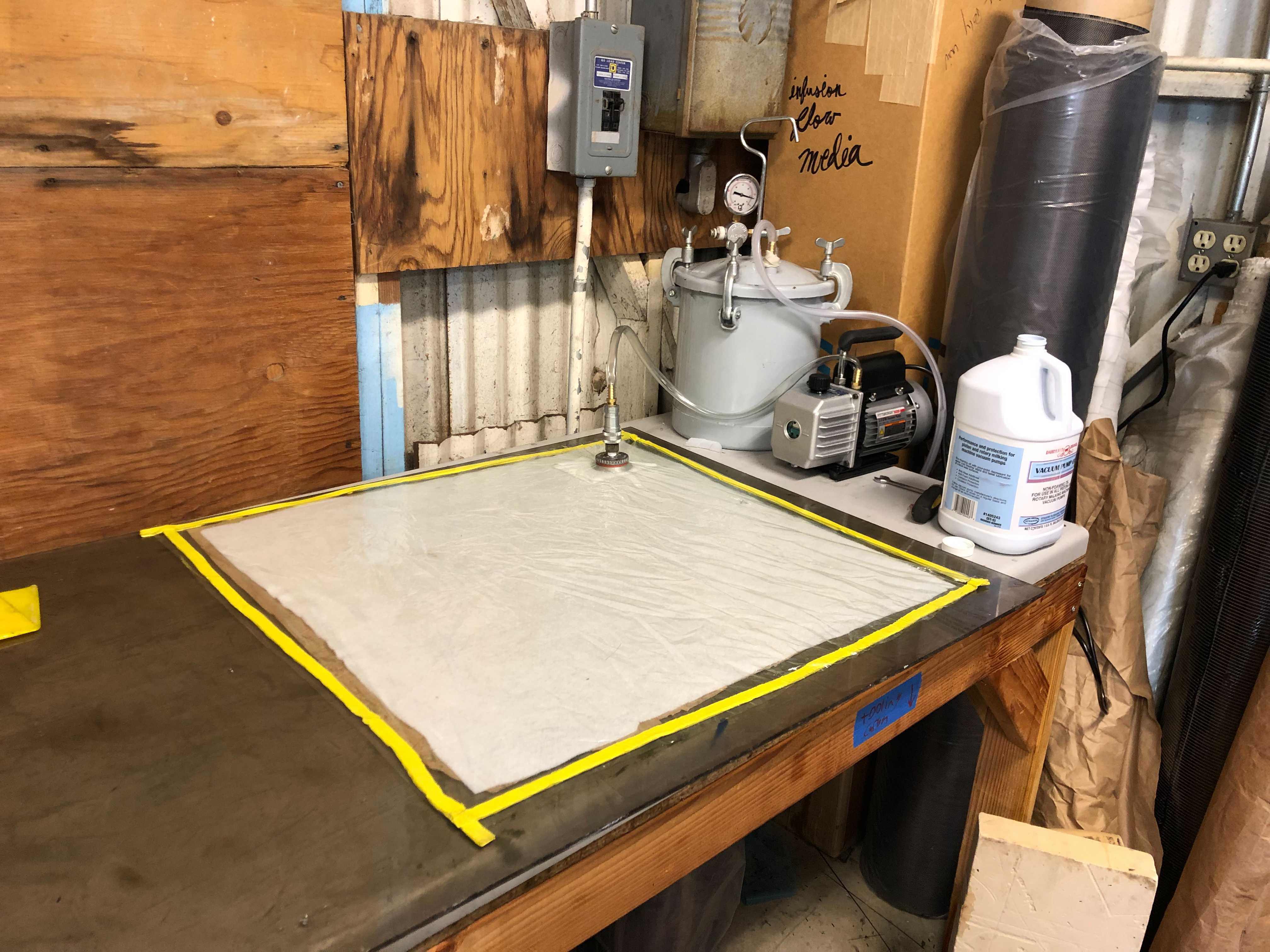
The nose cone tool was made by hand forming and cutting tooling carbon onto the buck. The tooling carbon was roughly equivalent to a symmetric and balanced 10 ply layup of our lower areal weight component carbon fiber composite structure. The nose cone tool consisted of a layer of 0 90 thin carbon sheet to mold well to the buck surface with 2-3 plys of tooling carbon elsewhere. Specifically, 3 plys of tooling carbon were placed in areas of high stress in the tool. These areas were the nose cone flange and the longer lofted sections of which tight geometry did not provide resistance to bending and bending was supported by the outer edges of the composite. We needed the rigidity within the tool to allow use to perform layups in the tool, resist deformation to atmospheric vaccum, and maintain an accurate nose cone geometry. Futhermore, making the tool 20-30x stiffer than our component layup gave us a longer tool life. This tool ended up being used for 3 years straight for all car/club nose cones. The resilience of the tool is critical under an unknown lifespan use by the club. After tooling carbon, was cut and planned to conform to the buck geometry, we were ready to perform the tooling carbon layup. I utilized epoxy weight to carbon fiber cloth weight to determine the goal cloth saturation based on previous chassis strength tests. All layups (tooling and component) were done via wet layup with west systems epoxy. The layup was performed and then we applied peel ply, breather, and placed the entire tool under vacuum within a vacuum bag. A fan was blown onto our buck-tool layup to attempt to prevent any deformation from our pla due to our exothermic epoxy. After our tooling layups, we trimmed the flange of both sides of the tool and then drilled holes through both flanges of either side. This gave us the ability to bolt together both sides of the tool and align the 2 halves to each other in preparation for a nose cone layup.
back plate
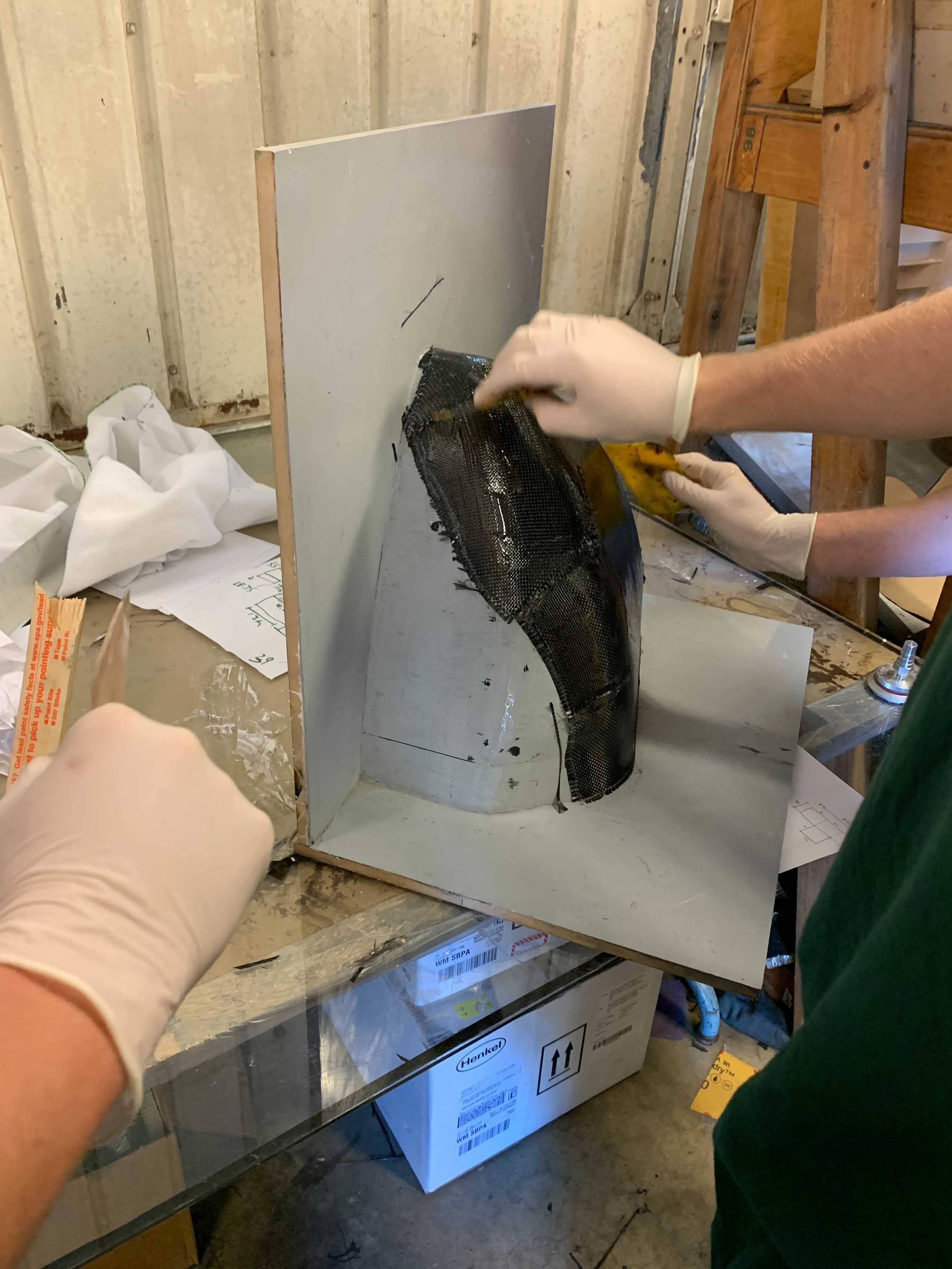
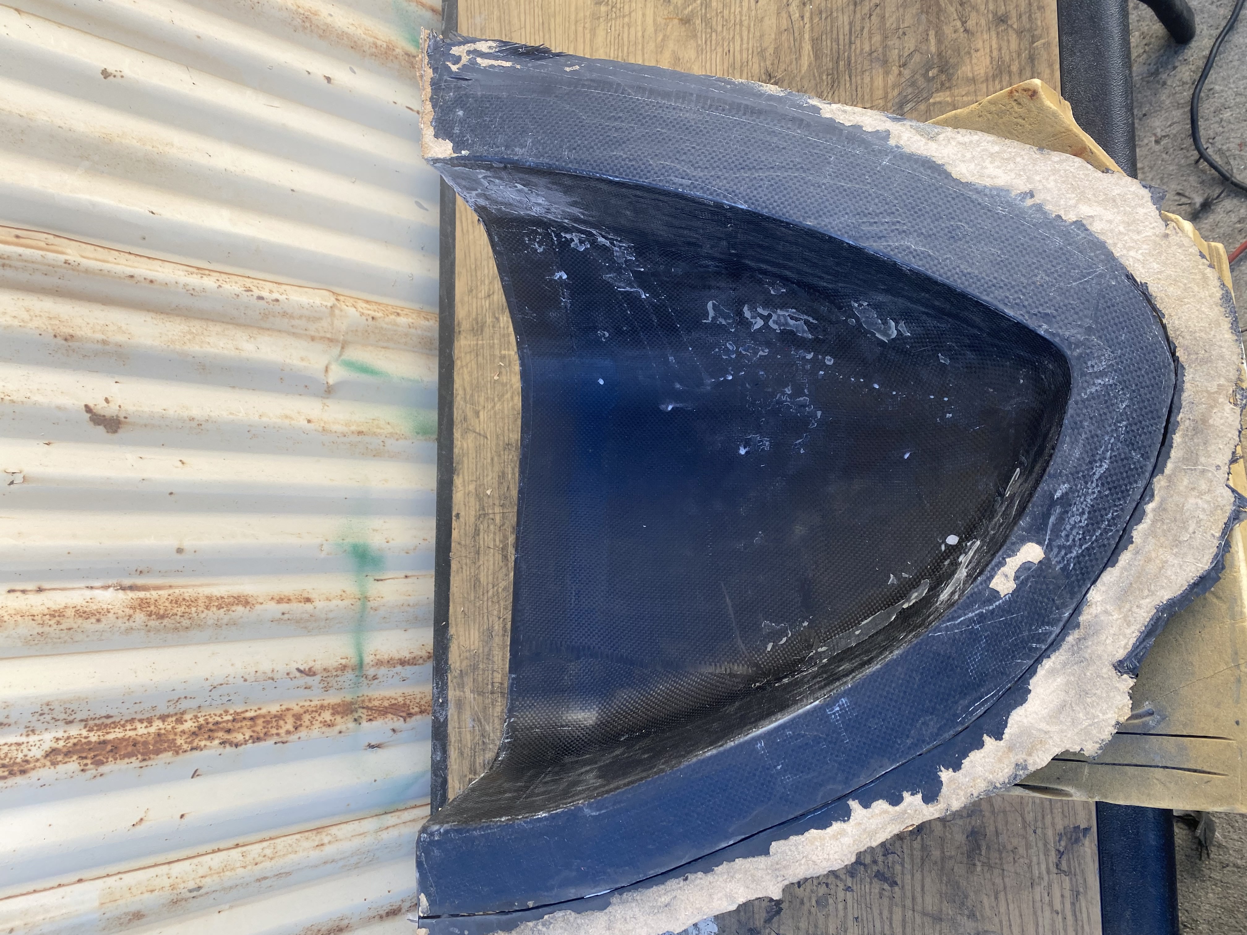
Tool with nose cone layup inside
First thin carbon layer of tool layup
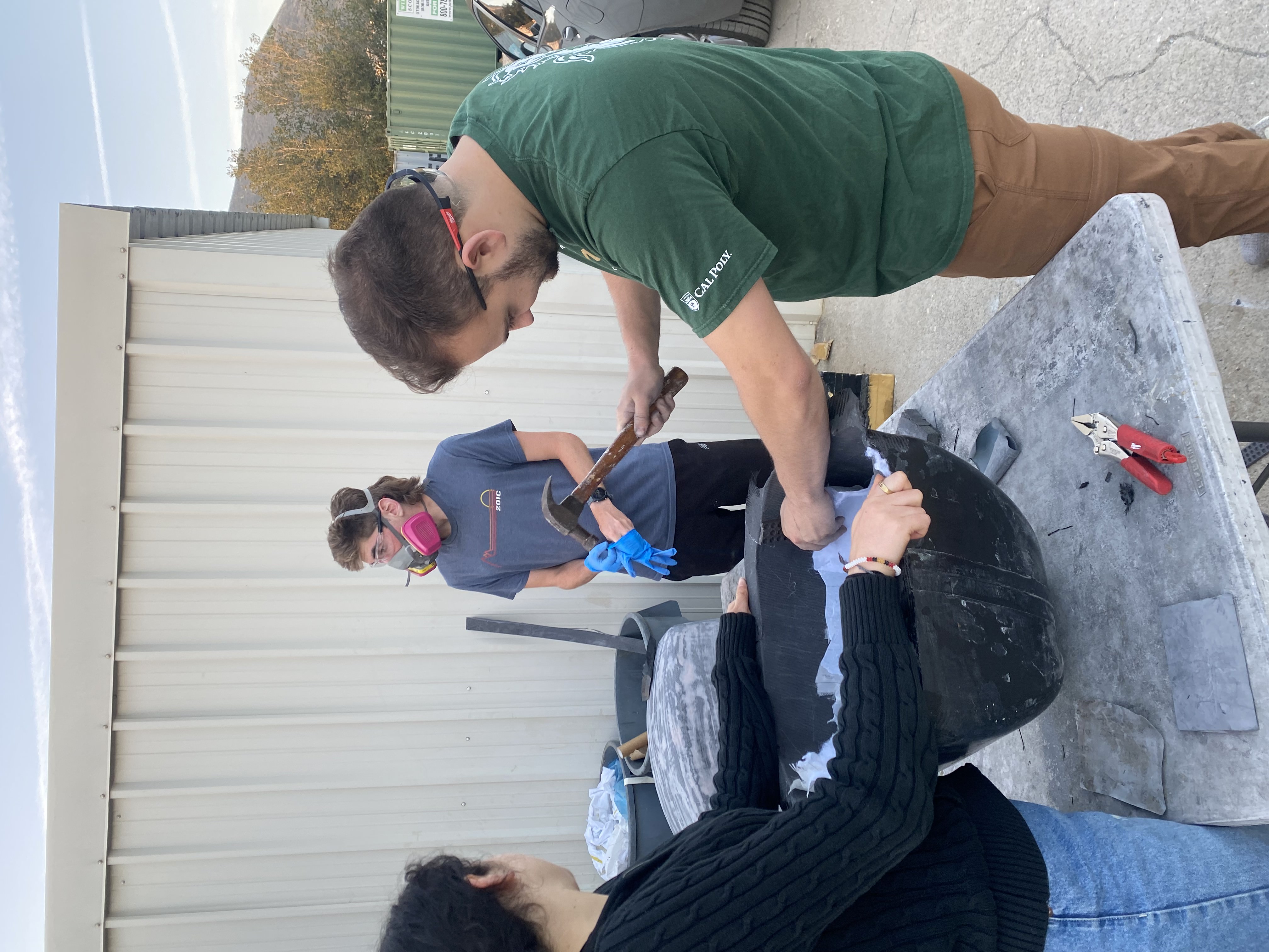
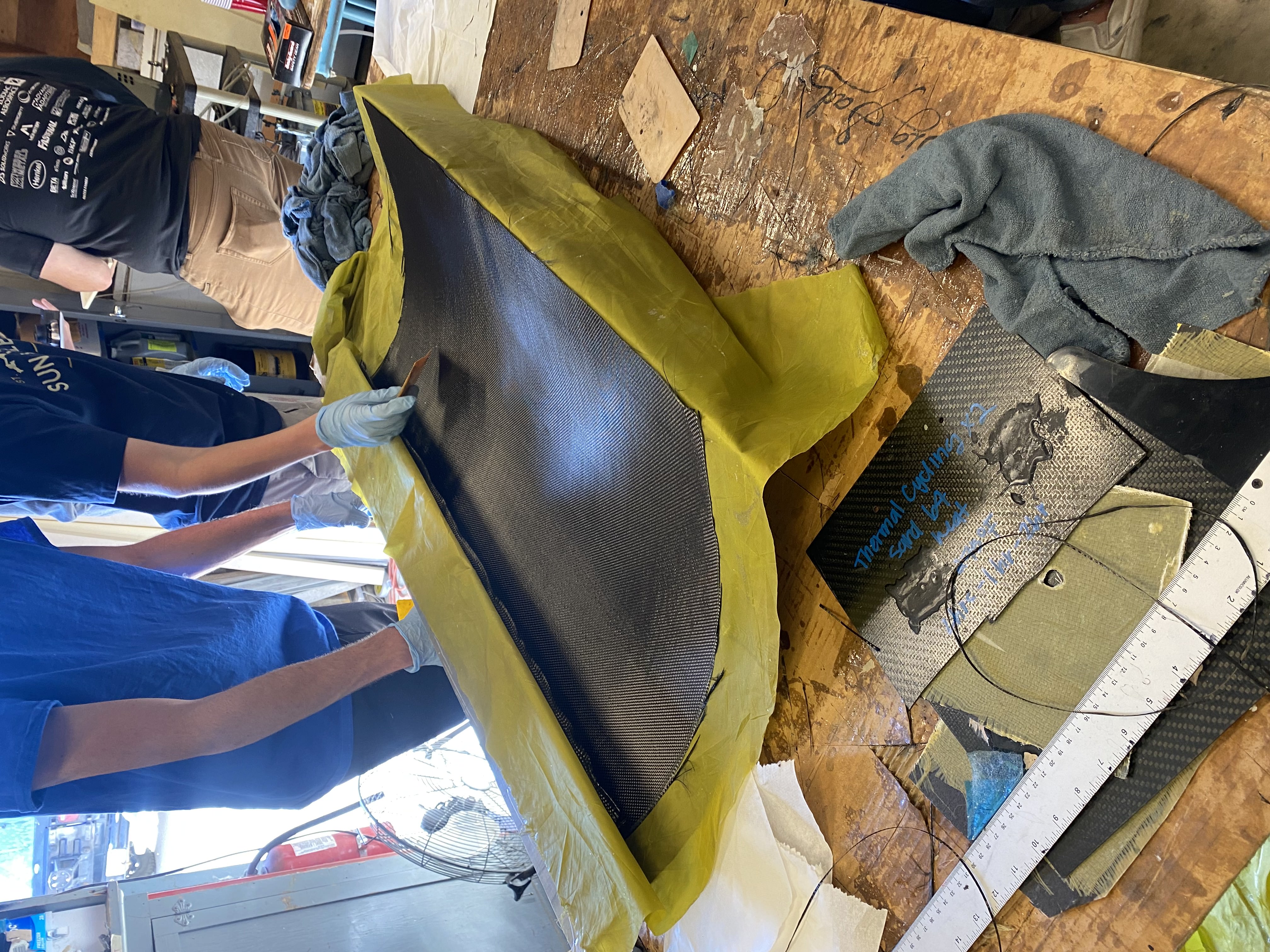
Detooling a nose cone

Other side of the tool buck
Trimming the tool flange
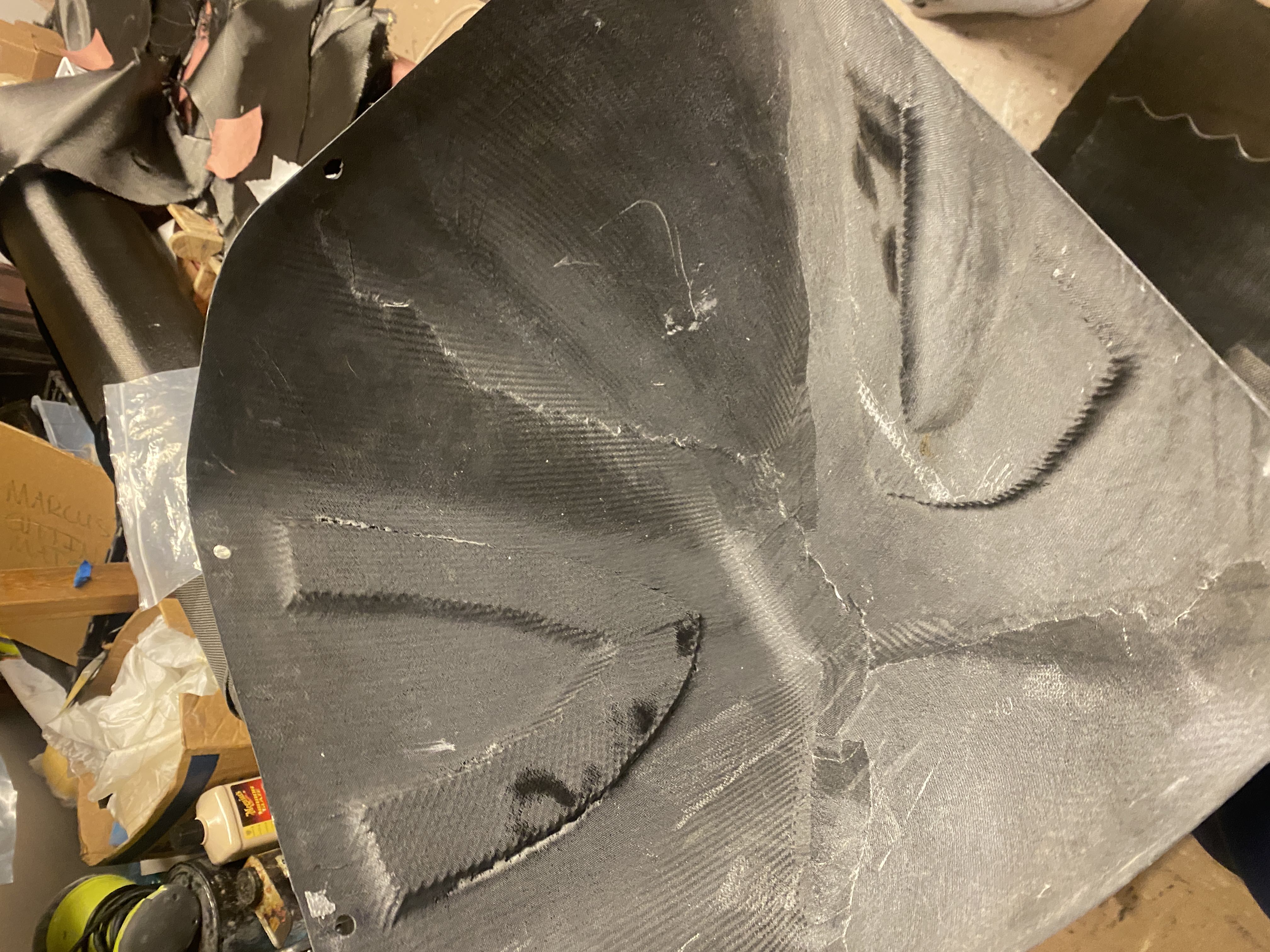
nose cone with core to prevent buckling
03
Aerodynamics Team
Aerodynamic Subsystem
The nose cone sections were sanded, aligned, and bonded. I then cut and nailed 2 pieces of mdf together at a 90 degree angle with the angle of the nosecone surfaces ensuring alignment. Each half of the nose cone buck was epoxied onto the mdf boards. After, thin layers of bondo were applied and sanded to minimize the presence of 3D printed layer lines. After bondo, a think layer of epoxy was applied as a last coat over the bondo to provide a uniform bonding and layup surface. The nose cone layup
back plate
Wings
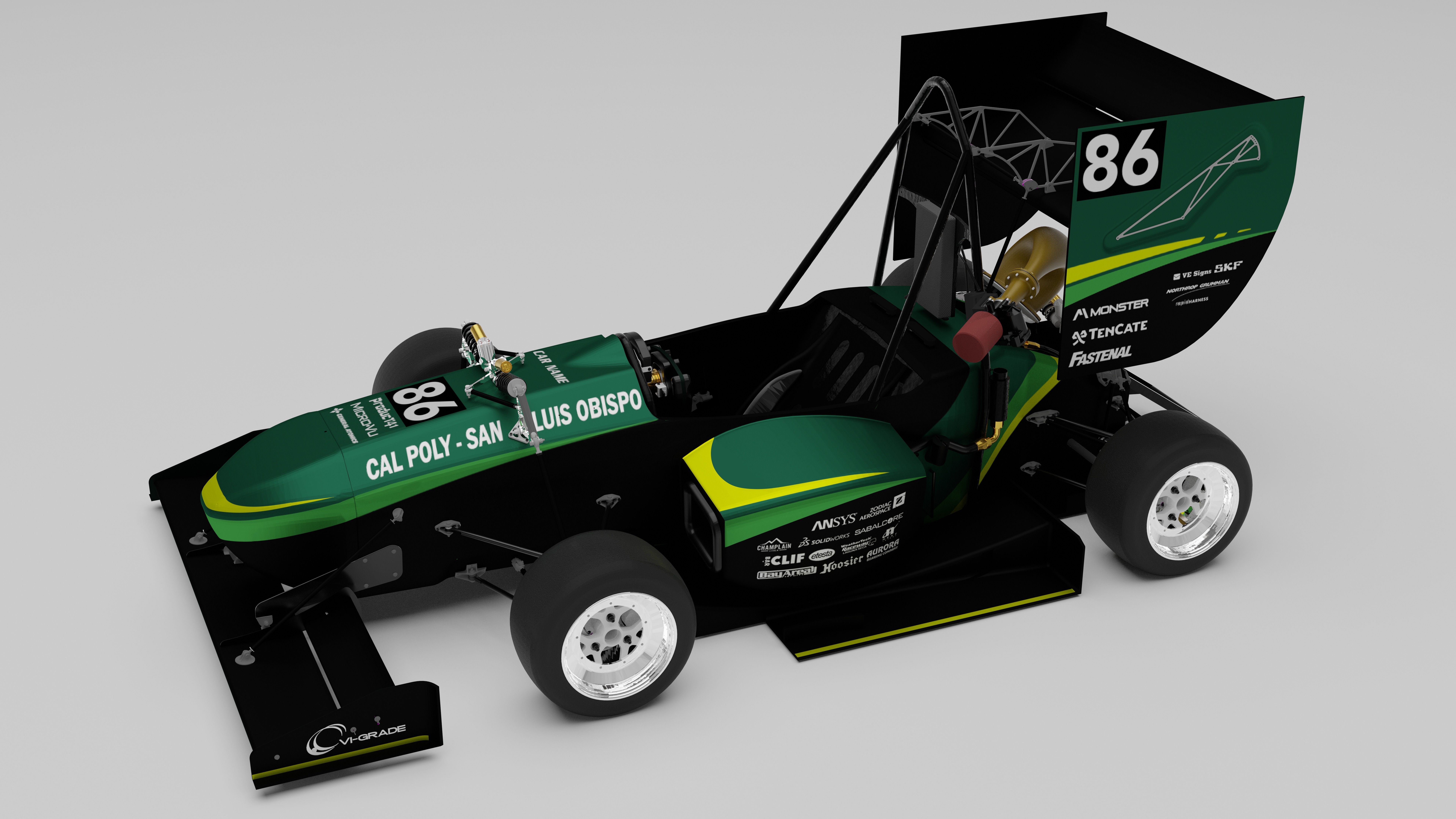
Full car cad
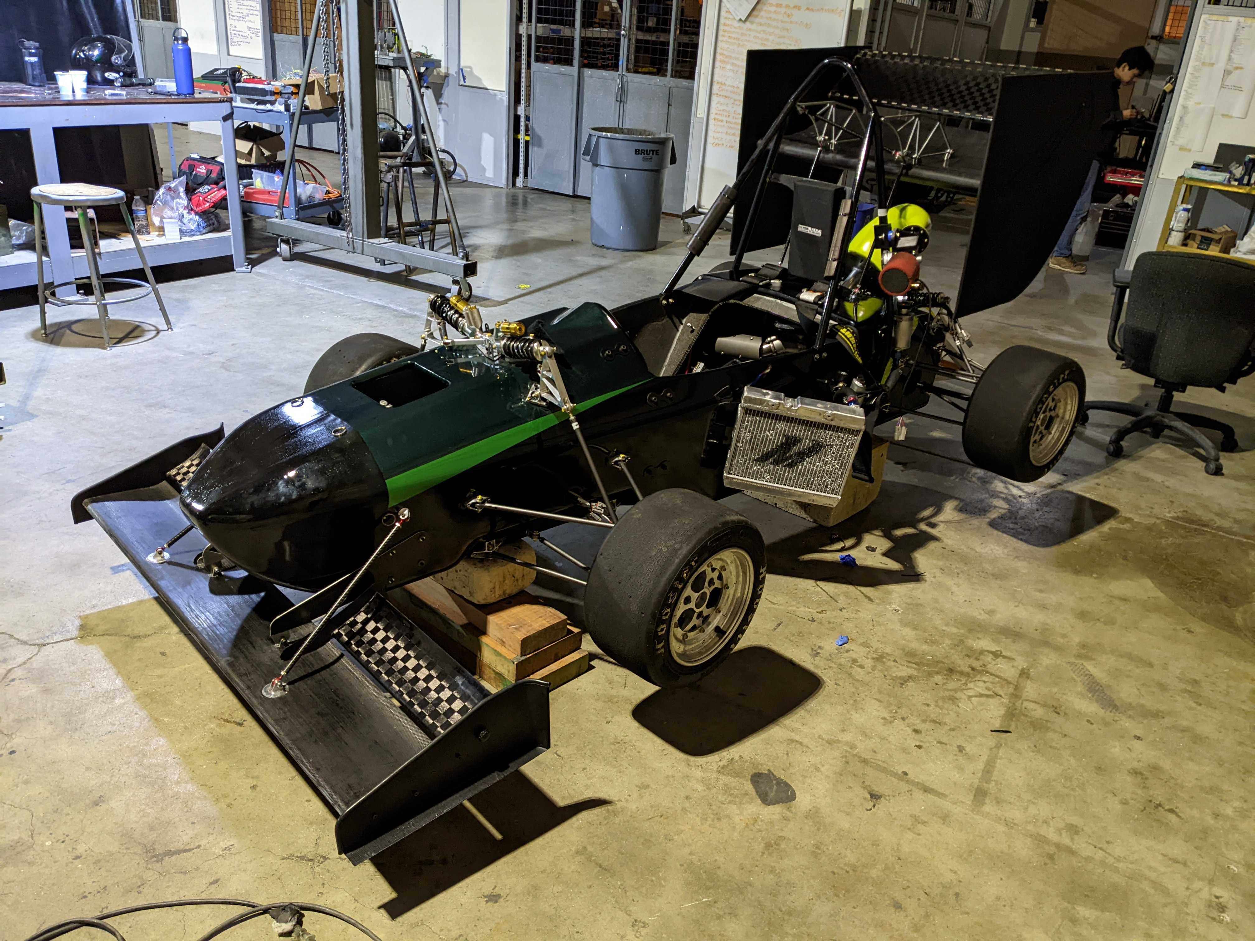
Car assembled
front wing endplates bent in fingerbreak
End plate layup
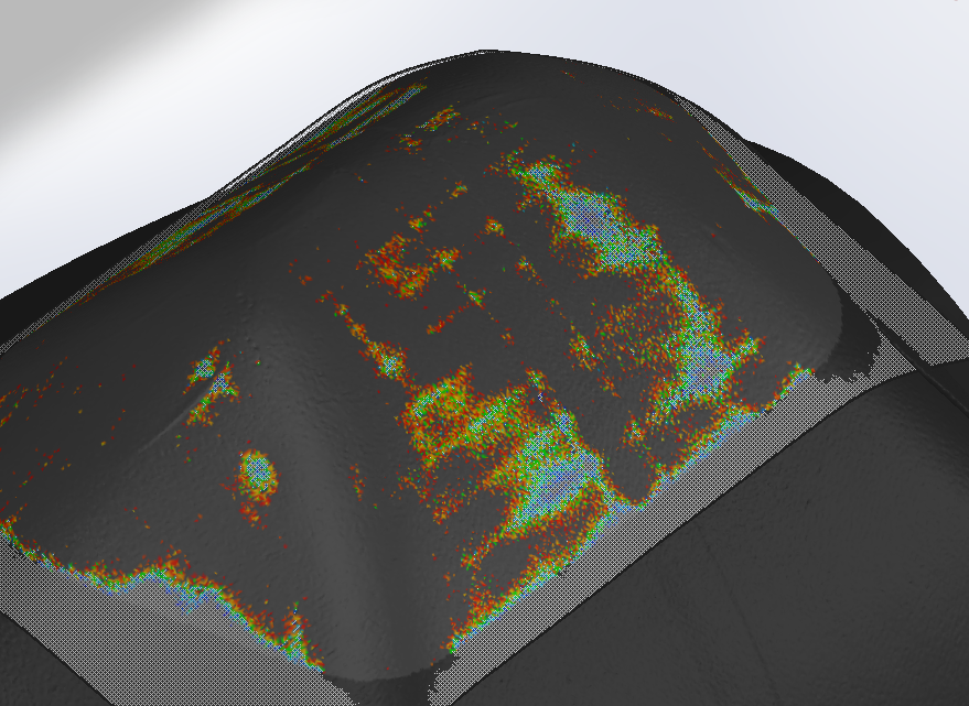
3d scan of nose cone - artifacting of print in final component!
Wing Skin
Back of tool
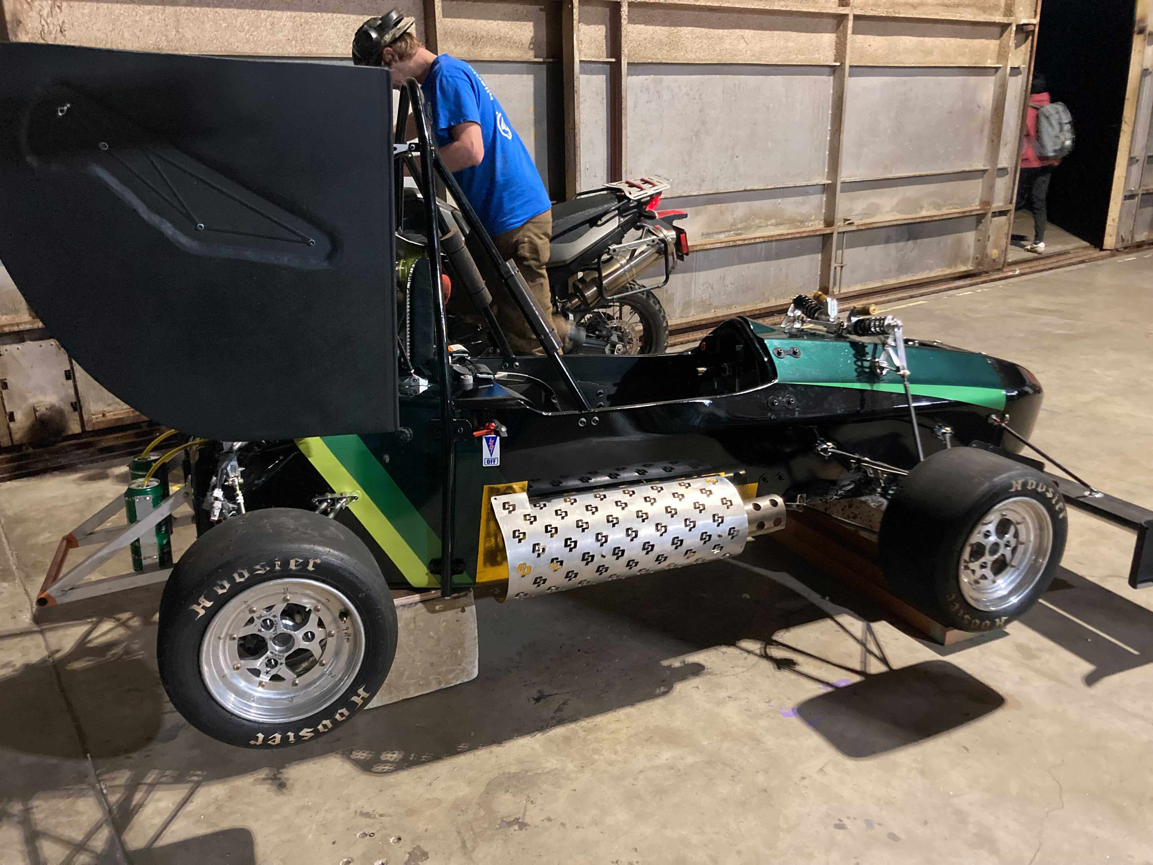
Side view of assembled car