LACUNA: Split Seat Tube Road Bike Design and Manufacturing
I designed and built a custom road bike frame using multiple manufacturing methods that combined a 3D printed steel tube connector, streamlined profile tubing, and tig welded reynolds steel. The project involved CAD design, FEA, and hands-on prototyping to create a truly unique frame.
01
Design Language Research
![[Cannondale]](/bikebuild/cannondale.jpg)
![[Deep Dish Rims]](/bikebuild/darkblue.jpg)
![[Dual Bend Seatstays]](/bikebuild/lightblue.jpg)
![[Paletti tube junction/split seat tube]](/bikebuild/paletti.jpg)
![[Raw Metal/Blade fork]](/bikebuild/silver.jpg)
![[Vintage Saxon dual seat tube]](/bikebuild/saxon.jpg)
![[Shallower rims/sand color]](/bikebuild/tan.jpg)
![[Vintage thin tube steel frame]](/bikebuild/vintageblue.jpg)
![[Raw metal/micrographic-esque frame]](/bikebuild/zipp.jpg)
Why These References
Due to this being a personal project, I wanted to design a frame that was unique and reflected my own desired design language. I drew inspiration from a variety of sources and builds. I began this project by researching:
What makes a frame beautiful?
What makes a frame feel fast?
What makes a frame seem fun to ride?
What elements of past frame design could reimagined with modern engineering and manufacturing techniques?
What makes a bike more than a mode of transport, but a technical work of art?
Throughout my research, I found that the most striking and visually grabbing bike had a multitude of small design elements working in harmony. Horizontal top tubes makes the bike seem to point forward and give a taut, disciplined posture. Slender steel tubes keep the frame looking light and nimble without collections of heavy volumes. Deep carbon rims on steel frame add visual weight and make it seem more planted and aggressive. They also add a temporal contrast of two eras of cycling meshing together, drawing on both modern performance trends and a sense of nostalgia for a previous era.
Immersing myself in these bespoke examples allowed me to build a mental library of proportions, details, materials, and visual relationships. This growing vocabulary did not prescribe a single form to copy; instead, it helped reveal the character of the bicycle I wanted to create. Like carving a form from stone, each reference provided another clue about what should be emphasized, refined, or removed, allowing the final design to emerge gradually from a broad field of possibilities.
02
Handling Characteristics & Vehicle Dynamics
Handling First, Geometry Second
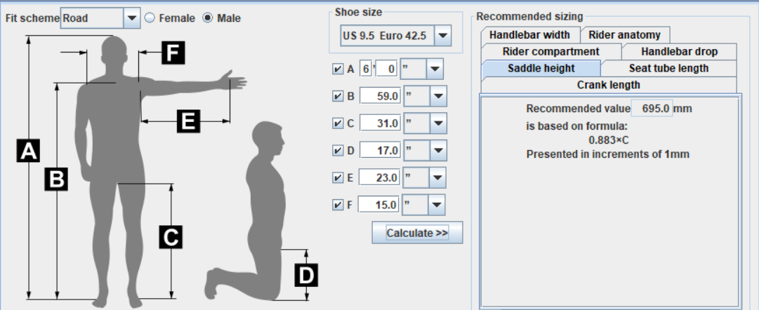
The bike was designed around my own personal measurments. I used a kinematic fit calculator to give an expected range for the correct crank length, seat tube angle, and bottom bracket drop for my own body. I then used the Patterson Control Model to gain more insight into the handling characteristics of the bike. I derived as many varaibles as possible from my handling targets and then I iterated on the geometry until I found a bike geometry that met my geometry goals and most importantly was manufacturable.
Initial bike fit/handling characteristics/geometry iteration in BikeCAD
Knocking Down Geometry Variables
Intially, I group variables into subsystems that are most relevant to each other. In reality, the geometry is a single system, and changing one variable can affect many others. However, to start to make progress and knock down some rough numbers for variables, the grouping allowed to dervie some expected rough values for certain bike parameters.
Trail is the lever arm through which lateral tire forces act to generate a self-aligning torque about the steering axis. It is the single number that most defines how a bike feels to steer: too little and the bike wanders and never settles, too much and it resists being turned at all. Industry benchmarks and rider handling studies put the useful band for a paved road bike at roughly 55–65mm (Bicycling Science, David Gordon Wilson and Theodor Schmidt, with contributions by Jim Papadopoulos), so I targeted 60mm — the middle of that band.
Because my fork offset was fixed at 50mm by what was available, trail could only be reached through the head tube angle. That inverted the usual design order: instead of picking an angle and accepting whatever trail resulted, I set the trail I wanted and solved the trail equation backwards for the angle that produces it.
Solving the Geometry
Head Tube Angle from Trail Target
With offset fixed and a trail target chosen, the trail equation has one unknown left. Solving it for θ sets the steering axis for the whole frame.
- R
- 334 mmeffective radius, 700c × 23mm tire
- f
- 50 mmfork offset, fixed by availability
- t
- 60 mmtarget trail, midpoint of the road band
Steering Torque at Peak Cornering
Trail converts a lateral tire force into a torque that tries to straighten the bars. Sizing that torque at the friction limit tells me what the steering interface has to resist, and what the rider has to hold against.
- m
- 75 kgrider and bike
- β
- 0.45estimated front load fraction
- Nf
- 331 N0.45 × 736 N
- μ
- 0.8dry pavement, conservative
- Fy
- 265 N0.8 × 331 N
Maximum Climb Angle
Taking moments about the rear contact patch and solving for the point where front tire load reaches zero gives the gradient at which the front wheel starts to wander and lift — the limit of usable climbing traction.
- x
- 0.455 mCG behind the front axle, x = βL at β = 0.45
- h
- 0.9 mCG height
- Nf
- 0 Ncondition — front wheel unloaded
Maximum Lean Angle from BB Drop
Bottom bracket drop trades two things against each other: a lower bottom bracket drops the center of gravity and makes the bike more stable, but it also brings the pedal closer to the road and limits how far the bike can lean before striking.
- dBB
- 74 mmcalculated from limb dimensions
- Lcrank
- 170 mmfrom leg kinematic fit
- R
- 334 mmeffective tire radius
Wheelbase & Mass Distribution
Wheelbase sets longitudinal load distribution and how sensitive the bike is to load transfer under braking and acceleration, while front- and rear-center decide how the rider's mass actually divides between the two contact patches for a given fit. Mine was not a free variable: the rear wheel and split seat tube packaging require a 380mm chainstay, which is short for a road bike and pushes weight rearward. I raised the seat tube angle to 74° — the top of the typical 72–74.5° range — to move the rider forward and compensate.
Front-center matters for a less theoretical reason: toe overlap. It is the horizontal distance from the bottom bracket to the front axle — 617mm on this frame — and it has to be long enough that the toe does not strike the front tire while turning and pedaling at the same time. With 170mm cranks chosen from a leg kinematic fit calculator, the current geometry leaves ~150mm between the center of the pedal and the tire.
Final Frame Geometry
Patterson Control Model
Static geometry only tells you what the bike is; it does not tell you how it behaves at speed. To check that, I ran the geometry through the Patterson Control Model, looking at four things: the speed at which the control spring changes sign, how firmly the bars push back against a steering displacement, how directly a steering input translates into path curvature, and how much hand force the fork flop demands as the bike rolls.
Handling Model Dashboard
Negative steering-spring and grip-force values indicate restoring feedback under the PCM sign convention. The spring crossing is not a complete weave/capsize stability prediction.
Read together, the four curves describe the same behavior from different directions. Yaw and roll authority both rise linearly with speed, and roll tracks a fixed fraction of yaw — the coupling that makes countersteering necessary. The control spring starts positive and crosses zero somewhere around walking pace, and past that point the model has the bars resisting a steering displacement rather than falling into it. The restoring torque that produces is small at the hand: quoted per radian it reads as a large number, but a 1° input at speed works out to a few newtons, well under a pound of force. Control sensitivity climbs with speed toward the band usually associated with direct road-bike steering rather than relaxed touring geometry. What these curves are good for is the shape and the sign of each trend — whether the geometry behaves the way a road bike should, and in roughly the right speed range. The magnitudes are a different matter, and the note below covers why.
Every number above is the output of a model, not a measurement. The Patterson Control Model is a deliberately simplified, linearized representation of a bicycle, and several of the inputs I fed it for this frame are still estimates rather than measured quantities, center of gravity height, roll radius of gyration and the combined rider-and-bike mass distribution most of all, none of which has been measured on the assembled bike. Those estimates matter: swept across the ranges I would consider plausible, the spring crossing moves by several miles an hour and the hand-force and sensitivity figures move by roughly a factor of two. The spring crossing also belongs to this simplified model specifically; it is not the bicycle's full self-stability speed, which depends on gyroscopic and inertial terms the PCM does not carry.
So I am treating these results for what they are: a design check that the geometry lands in a sane, well-documented band, not validated performance figures. The honest next step is measuring the real CG height and mass distribution on the finished bike, put it on the road with instrumentation, and re-run the model against what the bike actually does.
03
Frame Design
Starting Design Constraints, Goals, and Considerations
In light of the earlier design language, I want to incorporate a split seat tube, horizontal top tube, and a tight rear triangle. To knock down the overall frame geometry while being able to do extremely fast iteration, I started with BikeCAD to begin applying some of the handling characteristics geometry to the frame. Through bikeCAD I could begin to knock down actual frame dimensions and angles based on my kinematic fit and desired handling charcteristics. Furthermore, aspects such as fork offset, stem spacers, and and stem length could be quickly added. This intial process in BikeCAD allowed quick visual and iteration on aesthetics, geometry, and manufacturability.
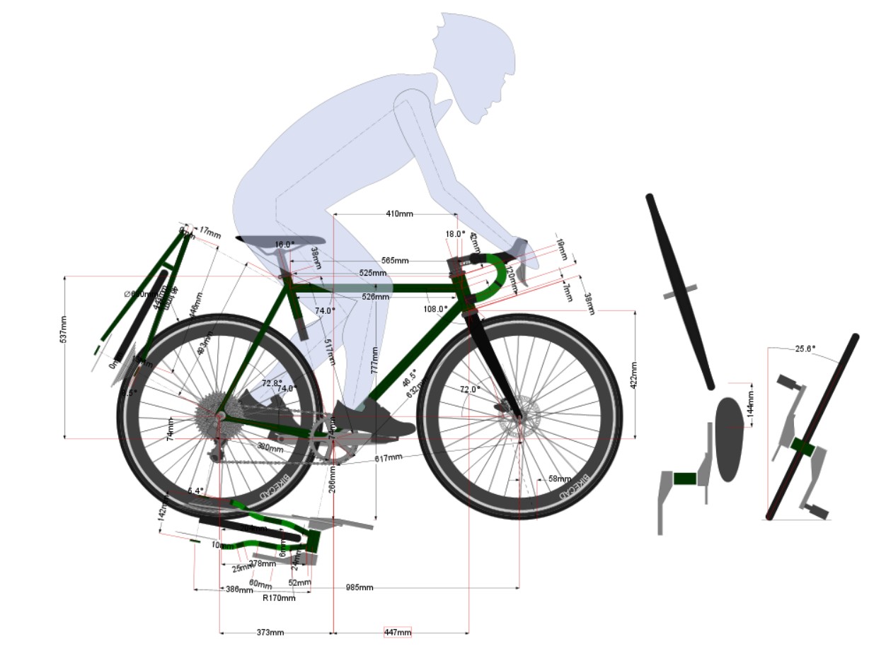
Frame geometry resolved in BikeCAD
Building the Frame in SolidWorks
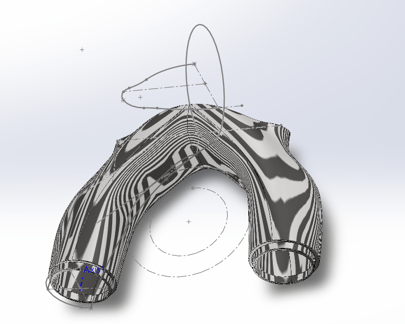
Due to the nature of the design, with custom tube profiles and a split seat tube, the frame had to be modeled for all the nuanced detail in soldidworks. I initially began by bringing over the BikeCAD geometry as a wireframe outline of the frame. From there I began modeling the tubes in their actual diameter and wall thickness. To achieve the tight fitment required to manufacture accuractely, I traced the streamlined metal tubing on a piece of paper then scanned the traced outline on a printer. After this, I imported the scanned profile into solidworks and scaled the scan based on caliper measurments. I then had the streamline tubing profile to model in solidworks.
![[Wire frame and starting tubes]](/bikebuild/FrameCADIP.png)
![[Seat tube yoke added in assembly]](/bikebuild/seattubejoiner.png)
![[Streamline tubing before yoke]](/bikebuild/streamlinebeforejunction.png)
![[Streamline tubing geometry]](/bikebuild/streamtubegeo.png)
![[Chainstay yoke on frame]](/bikebuild/chainstayyokeonframe.png)
![[Seat tube yoke in CAD]](/bikebuild/seattubejoinercad.png)
Seat Tube Yoke
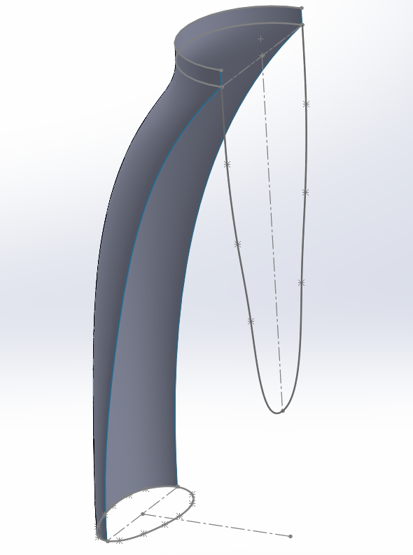
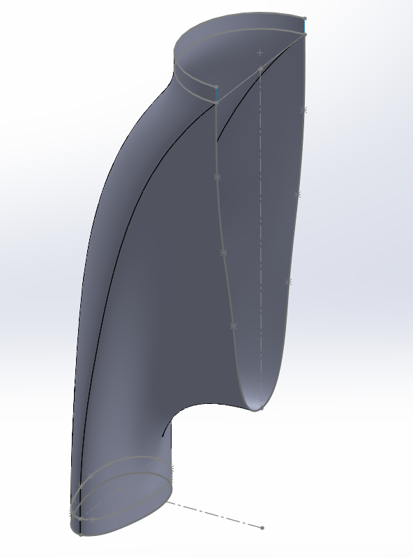
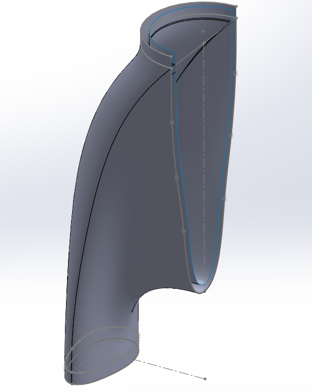
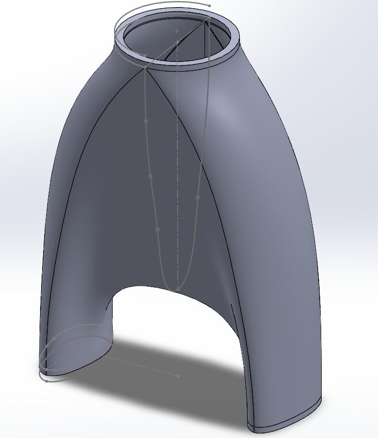
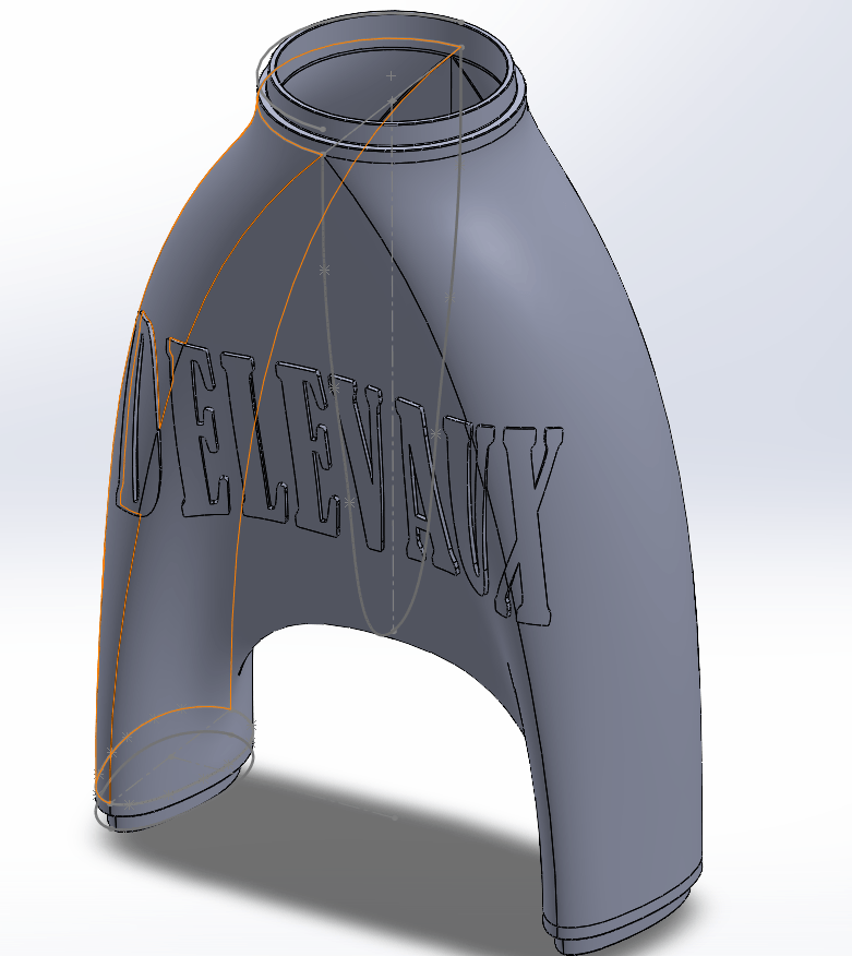
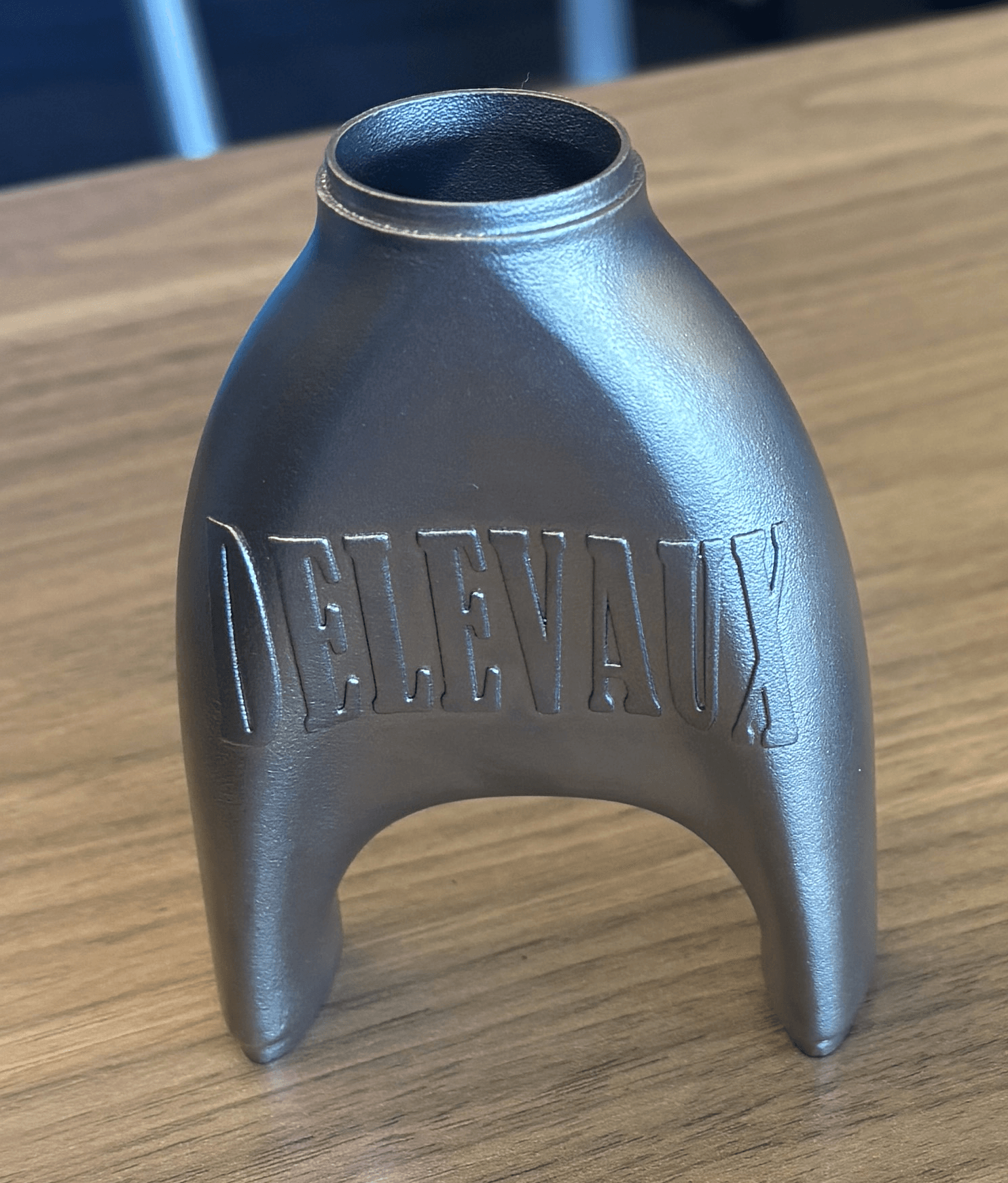
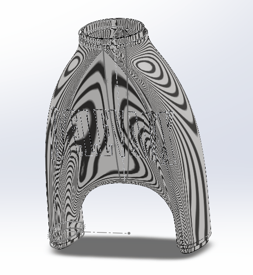
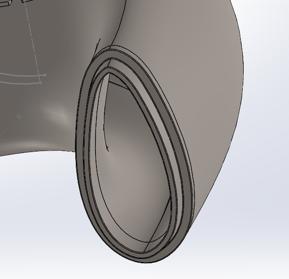
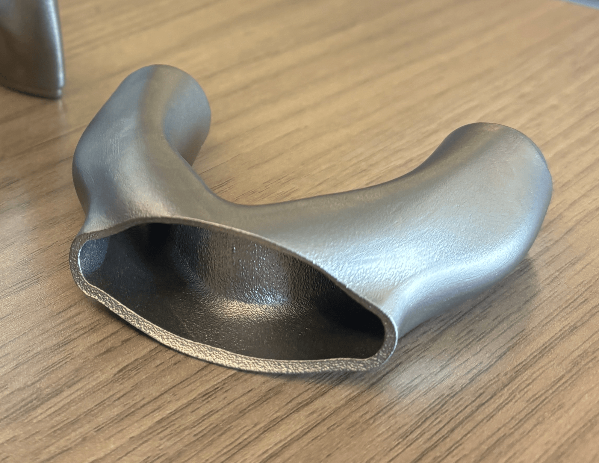
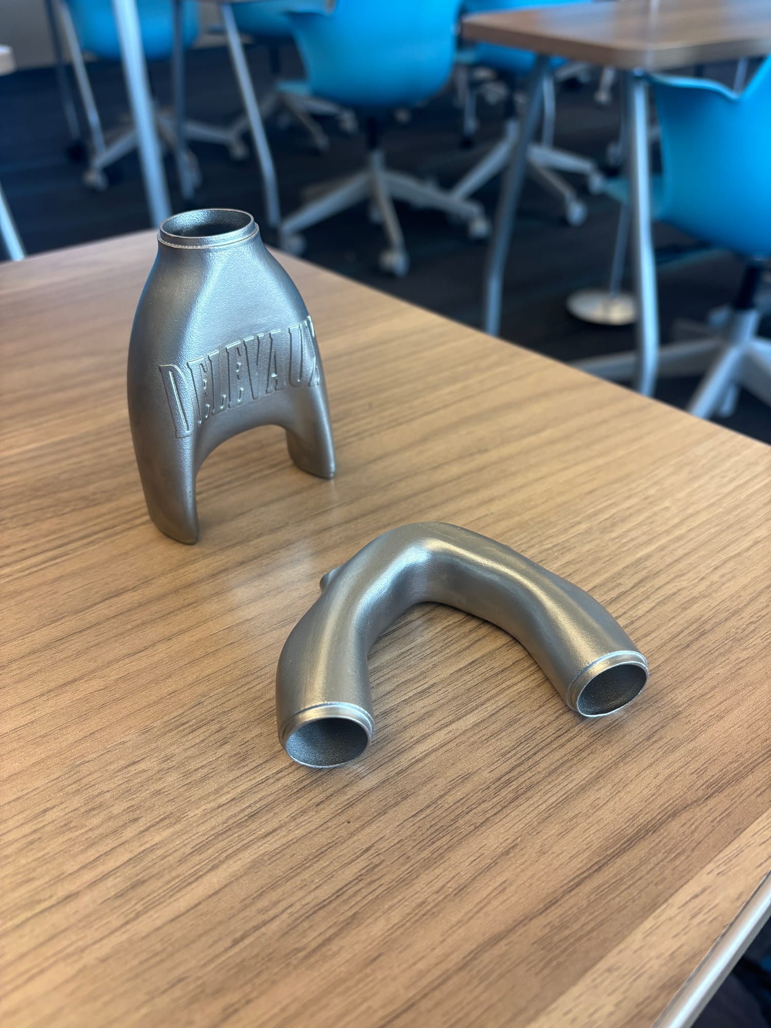
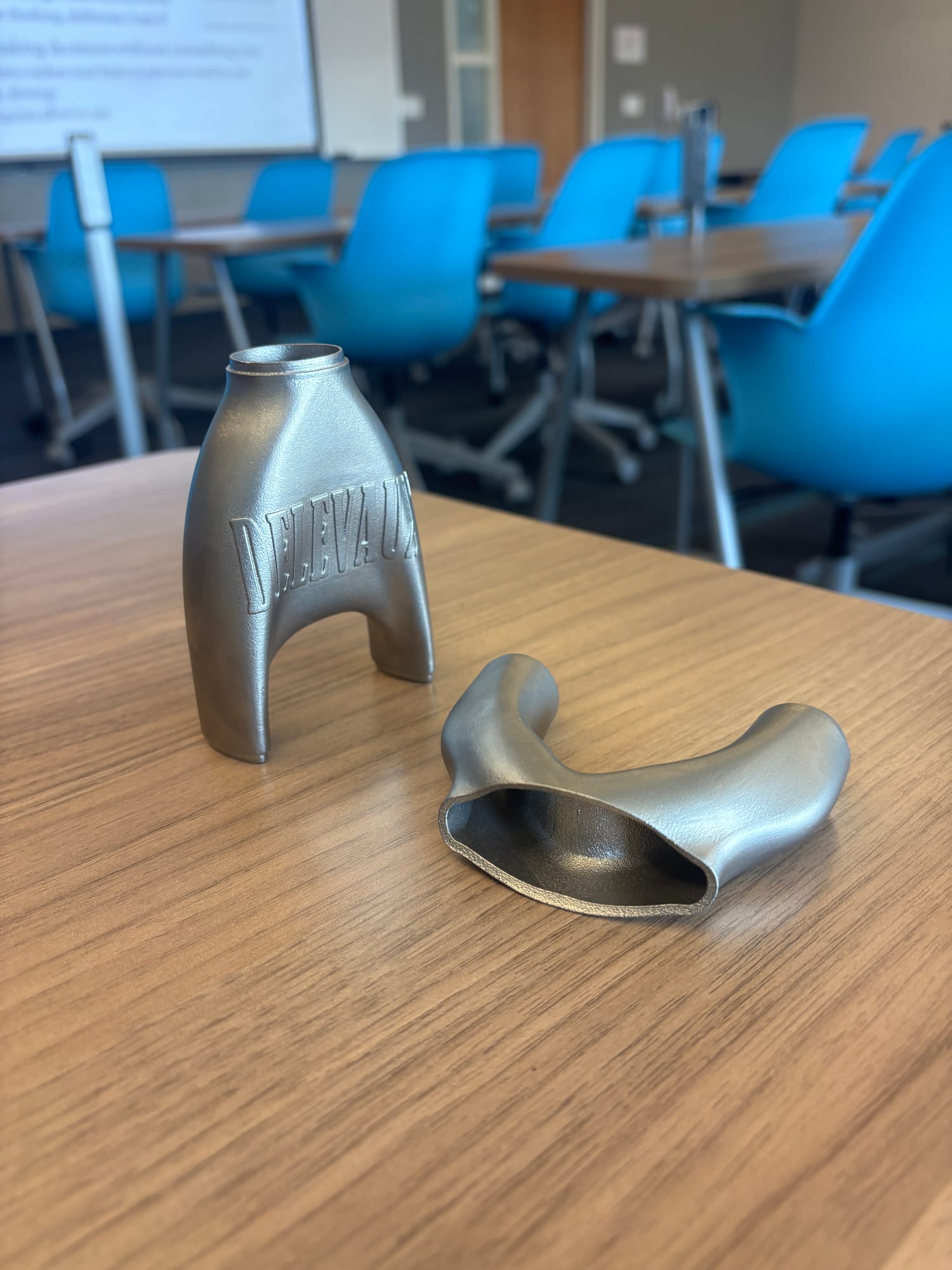
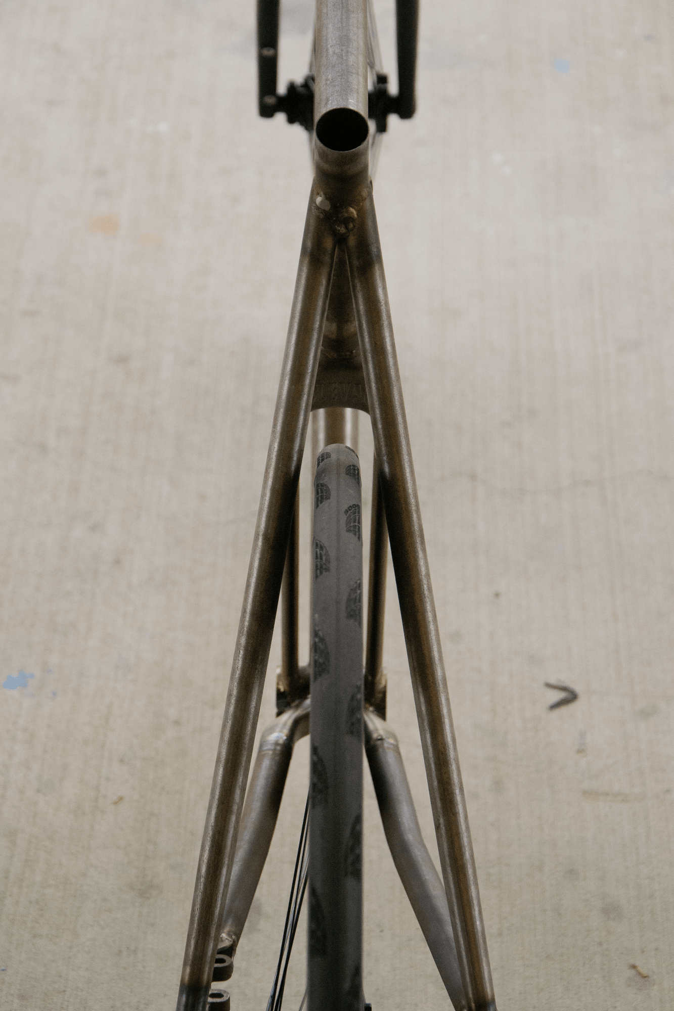
The seat tube yoke (the piece connecting the two streamline tubes from the bottom bracket to the full size seat tube) requires adapting 2 streamline tubes to a full size seat tube. This is not easily achievable with basic solid modeling. Therefore this part requires surface modeling to attain the proper geometry. Due to the nature of the complex curves and organic geometry, I realistically had 2 manufacturing options: Metal Casting or Metal 3D printing. Metal 3D printing provided the cheapest and fastest possiblity to create this part. However, because the yoke needed to be welded to 4130 steel, I needed a similar weldable steel to properly join these materials. I went with 316l stainless steel for its ability to properly mate to the 4130 and its ease of manufacturability. A few images of that process are below.
Chainstay Yoke
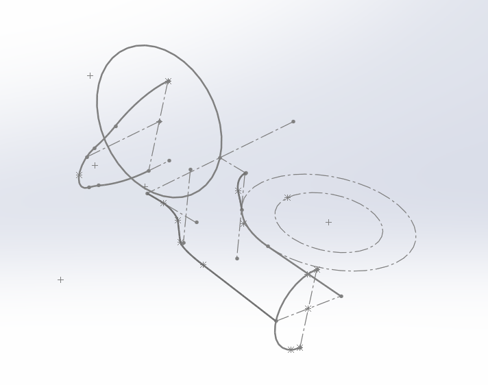
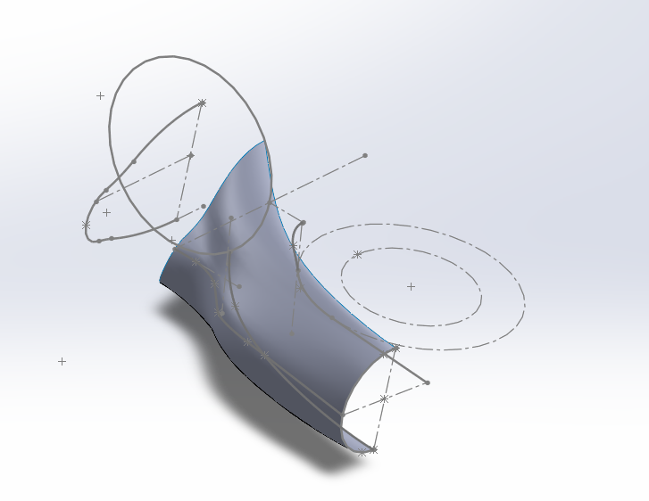
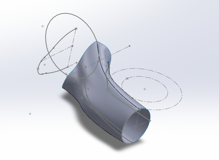
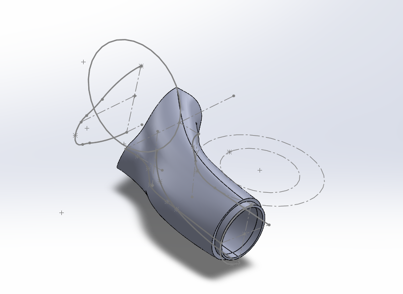
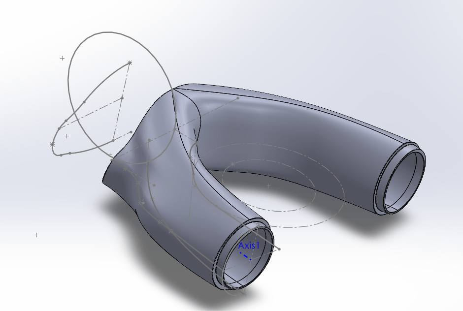
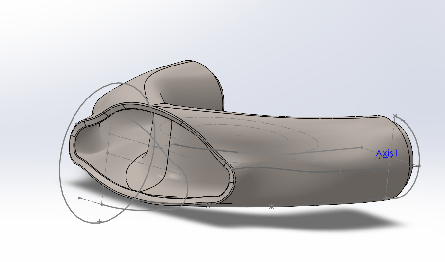
The chainstay yoke is the most loaded and most geometrically constrained part of the frame, it has to clear the tire and the drivetrain while tying both chainstays back into the bottom bracket shell. Due to the same lofted geometry as the seat tube yoke, the chainstay yoke was also surface modeled. Notable features on the designed yoke include lines pointing to the center of the yoke and room/draft angle around the bottom bracket joint. These features greatly aid in the manufacturability of the yoke by helping with locating in the fixture and allowing the cup on the tig welding torch to easily pass around the joint.
04
Analysis & FEA
Split Seat Tube Design
The split seat tube breaks away from the conventional single-tube designs and required careful consideration of the resulting structure. I could not rely on convention to ensure structural integrity. I wanted a design that would perform well while hitting the desired silhouette. As seen above, in old examples, they often used thinner circular tubes around the tire to achieve this design. However, with some quick napkin math, you will find that stiffness losses are large. Tube stiffness ~D^4, therefore, 2 smaller tubes are orders of magnitude less stiff than one larger tube even though there are more. To compensate but still hit packaging constraints I went with ovalized streamlined tubing to gain back the fore to aft stiffness while relying on the large distance between the tubes for lateral stiffness. The two configurations differ almost entirely in how material is distributed about the bending axes, which is what the interactive comparison below explores.
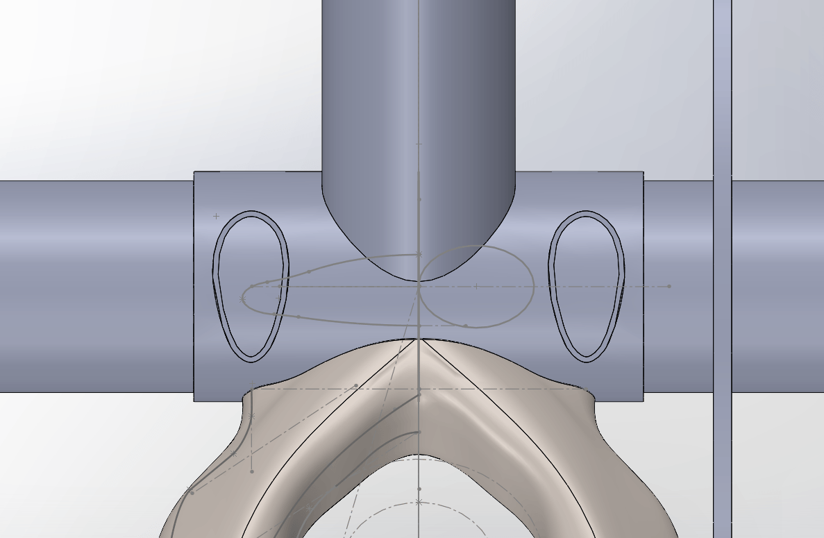
Cross section at the bottom bracket
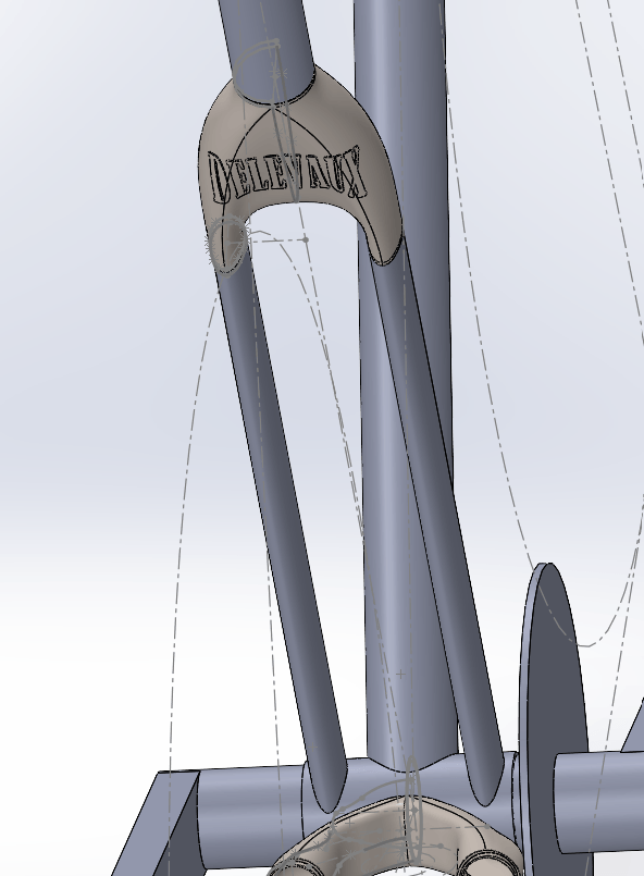
Split seat tube configuration
Where the Stiffness Comes From
Both configurations below are 4130 chromoly, so nothing separating them is a material property — it is entirely how the material is arranged around the bending axes. Drag either set of sliders and the cross sections, the numbers and both curves update together. The conventional tube is symmetric, so its stiffness is the same in every direction and its curve is flat. The split pair is not: spreading two tubes apart laterally pushes area away from the lateral bending axis and the parallel-axis term dominates, while running the major axis fore and aft is what keeps the pair from giving up too much in-plane stiffness for the material it uses.
Conventional round seat tube
Split seat tube — two streamlined tubes
| Section property | Conventional | Split | Split ÷ conventional |
|---|---|---|---|
| Lateral bending EI (N·m²) | 1,320 | 18,078 | 13.70× |
| Fore-aft bending EI (N·m²) | 1,320 | 1,143 | 0.87× |
| Lateral second moment I (mm⁴) | 6,437 | 88,184 | 13.70× |
| Fore-aft second moment I (mm⁴) | 6,437 | 5,576 | 0.87× |
| Mass per unit length (g/mm) | 0.584 | 0.755 | 1.29× |
| Lateral stiffness-to-weight (N·m² per g/mm) | 2,261 | 23,929 | 10.59× |
This is an analytical section comparison, not FEA. It computes closed-form second moments of area for a hollow circle and a pair of hollow ellipses, using the parallel-axis theorem where the tube spacing carries material away from the bending axis. It is a way of seeing where the stiffness in a split seat tube actually comes from.
//
05
Manufacturing
Manufacturing Prototype
To ensure both the design and my skills were capable of making the full bike. I wanted a test ground to understand how miter clearances, tig welding, and tube bending all worked and influence each other. I decided to make a cheap, quick, and easy bike rack to practice and gain understanding on before moving on to final production.
[Bike Rack Tubes cut and mitered on drawing]
![[Bike Rack Tubes cut and mitered on drawing]](/bikebuild/rack.JPG)
Working With Extreme Urgency
The manufacturing phase of the project was planned at 4 weeks to go from accepting tube shipment to frame rolling. This was especially difficult considering this was a side project with limited shop hours available. To meet this incredibly tight deadline, I had to think 10 steps ahead and premtively plan around and through any possible gating factors. Anything that could be or might be an issue had to be de-risked and extensively planned around so nothing could stop production. A highlightt of this is when my metal 3d printed yokes were delayed by a week. I needed them to start final fitment and for starting frame tacking. To priotize every minute in the shop, I printed the joints out of plastic and began all final assembly and tube fitment/filing with the plastic versions. Therefore, as soon as the metal 3D prints hit our shipping dock, I could plug and play and start welding. Not only was this an engineering challenge, but it was also a project management, shipping logistics, and supplier challenge as many moving parts had to align perfectly to meet production targets
[Plastic seat tube yoke used for fitment before metal 3D prints arrived]
![[Plastic seat tube yoke used for fitment before metal 3D prints arrived]](/bikebuild/framejigplastic.JPG)
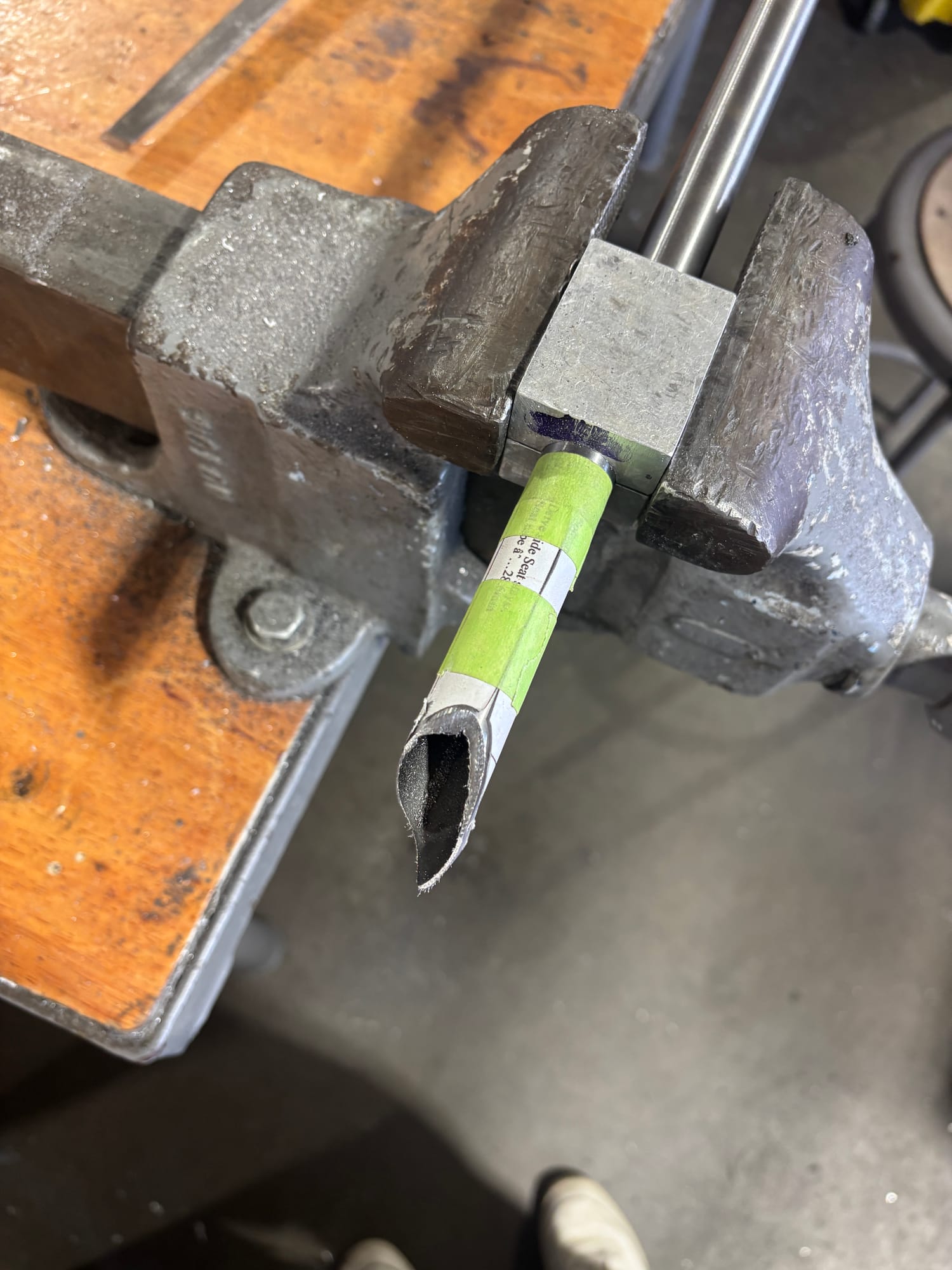
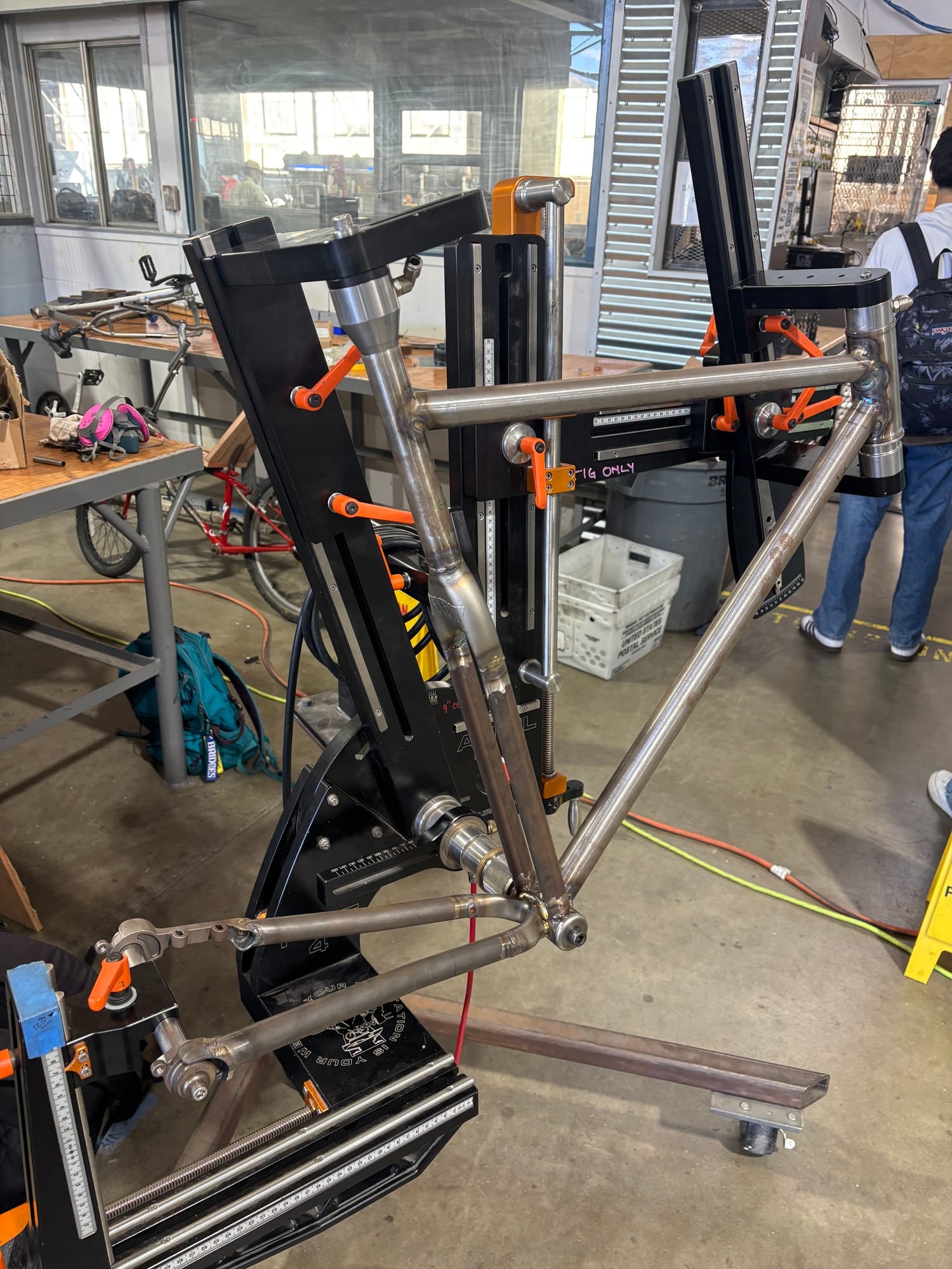
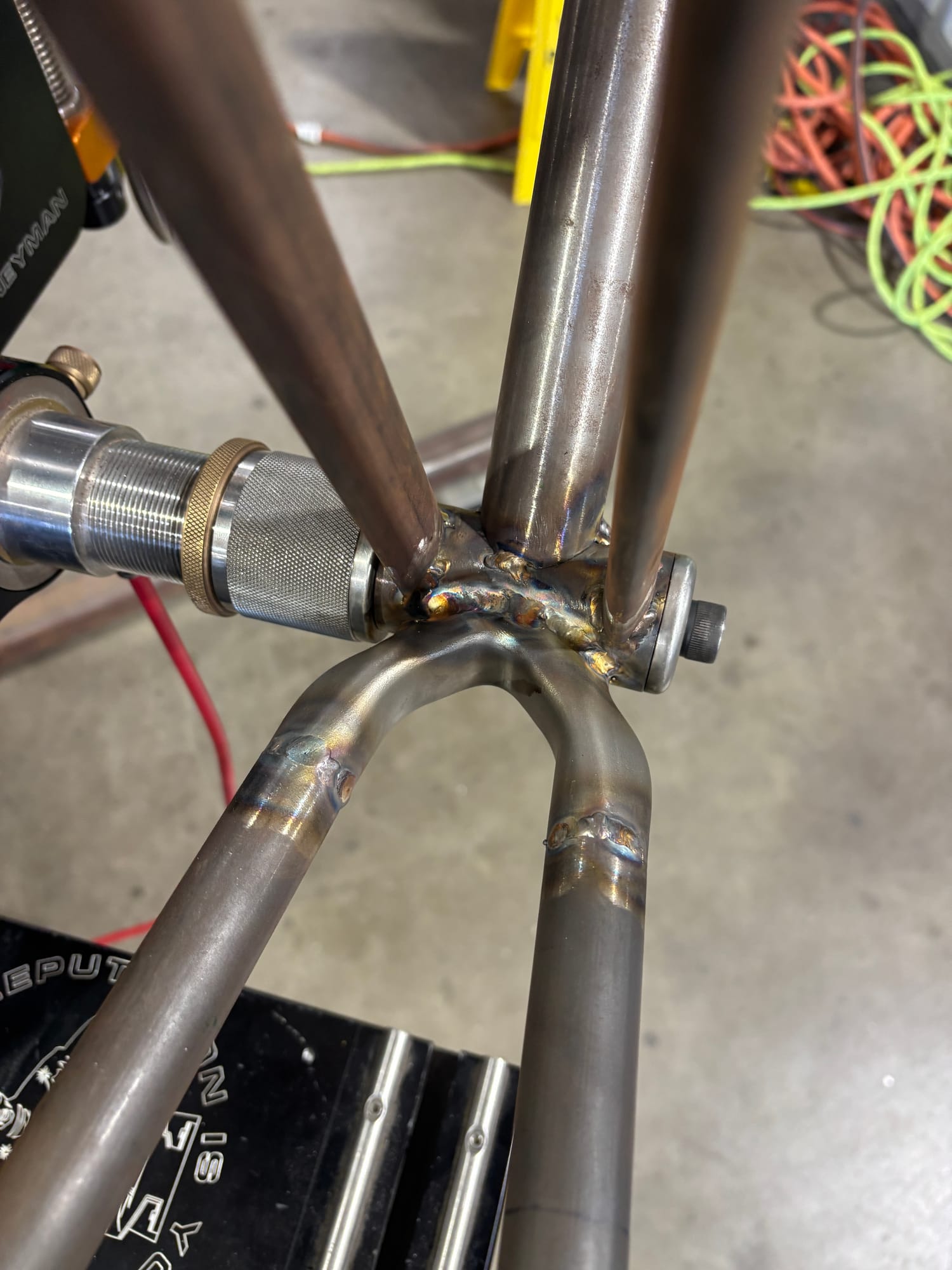
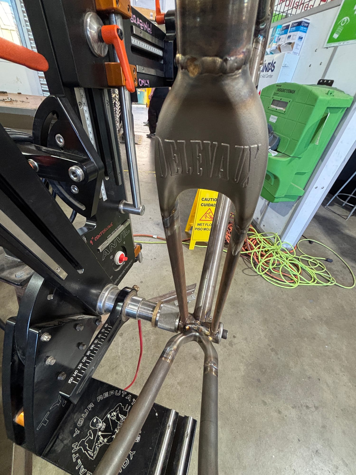
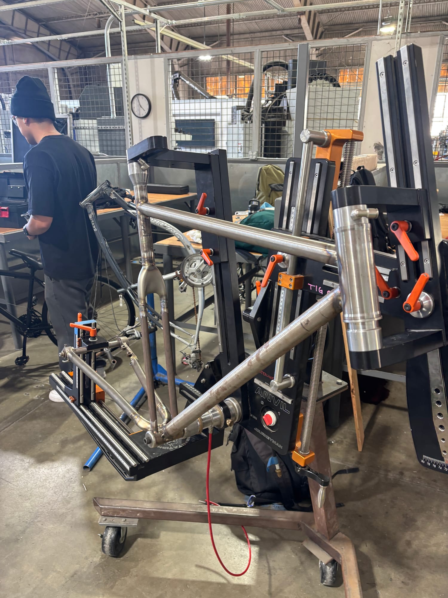
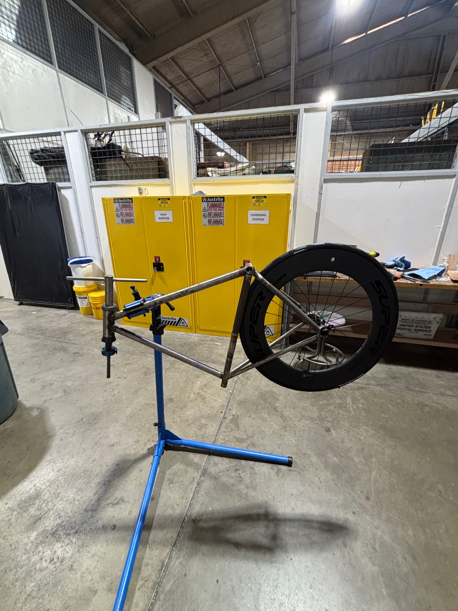
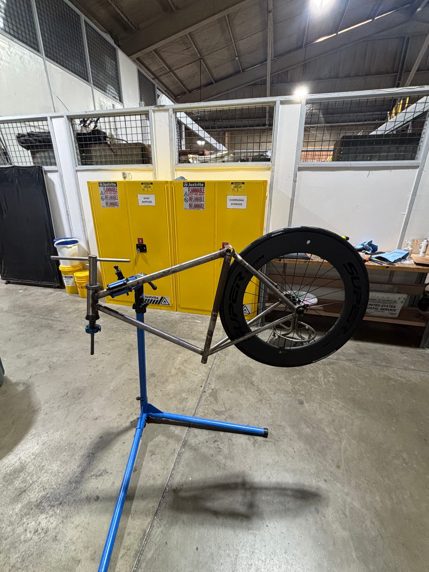
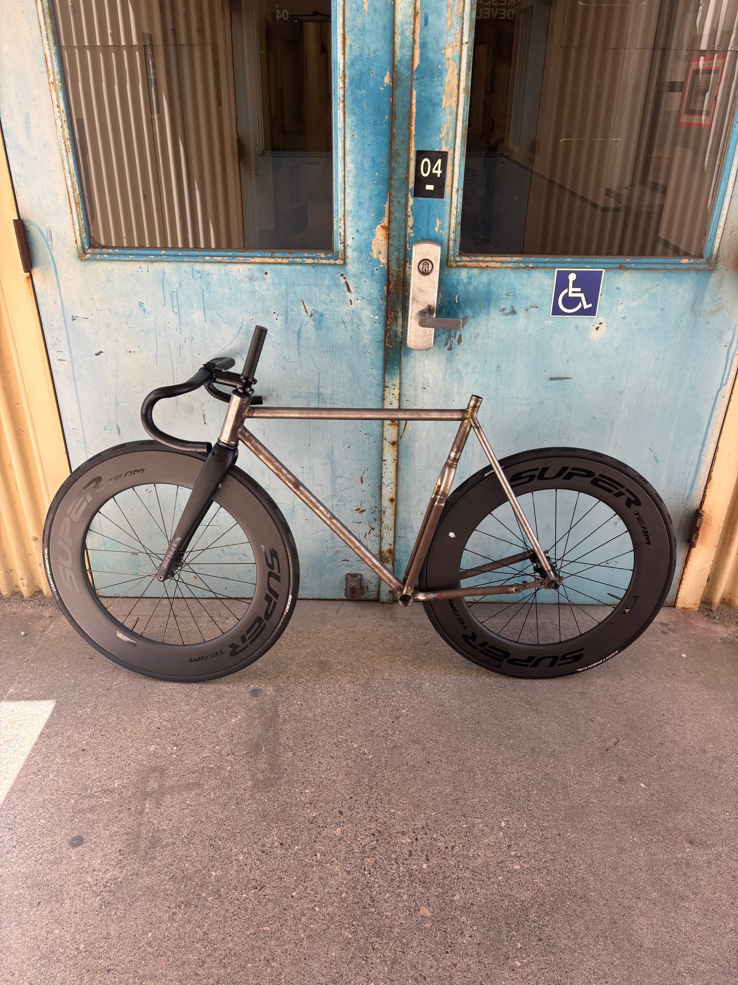
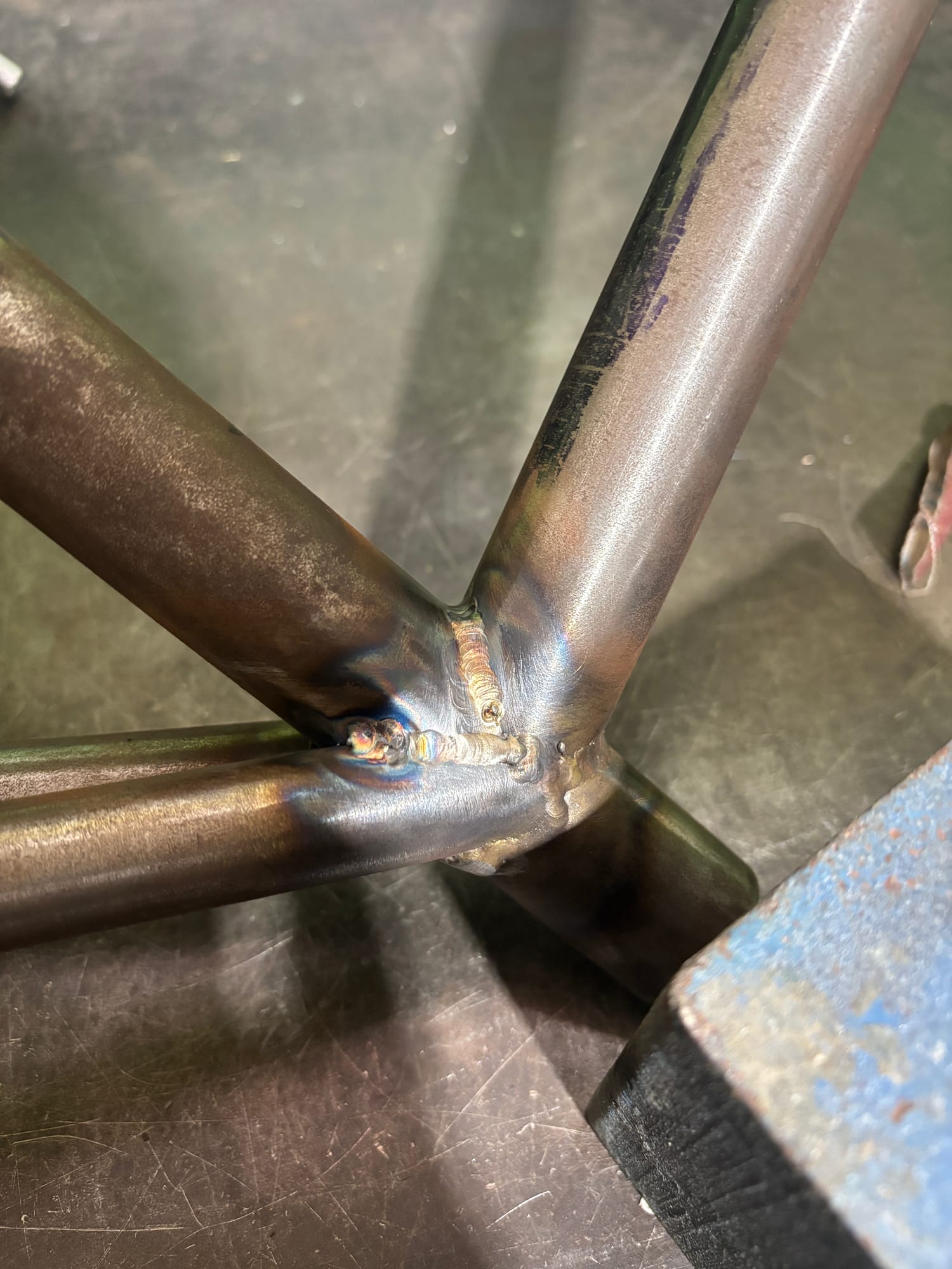
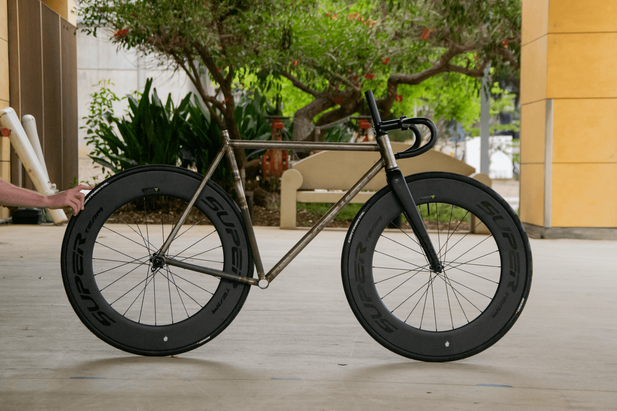
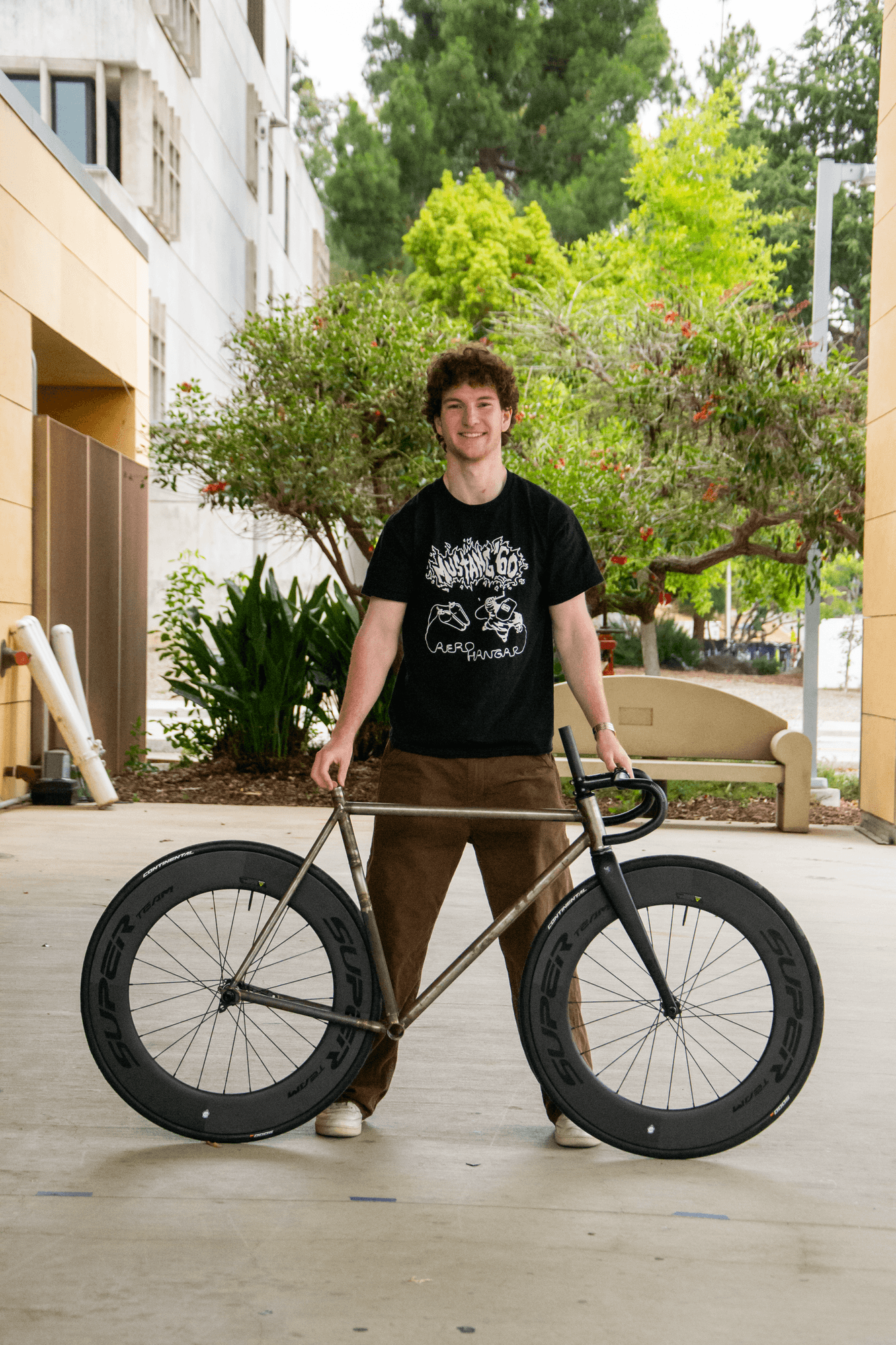
I could write about this build all day — but I'll let the pictures do the talking.

06
Results
//